
Road surface state estimating apparatus, road surface friction state estimating apparatus, road surface state physical quantity calculating apparatus, and road surface state announcing apparatus

a technology of road surface and estimating apparatus, which is applied in the direction of digital computer details, process and machine control, instruments, etc., can solve the problems of long calculation time, large number of errors, and difficulty in meeting requirements, and achieve the effect of accurately estimating the road surface friction sta

Inactive Publication Date: 2007-07-24
TOYOTA CENT RES & DEV LAB INC
View PDF10 Cites 27 Cited by
  • Summary
  • Abstract
  • Description
  • Claims
  • Application Information

AI Technical Summary

Benefits of technology

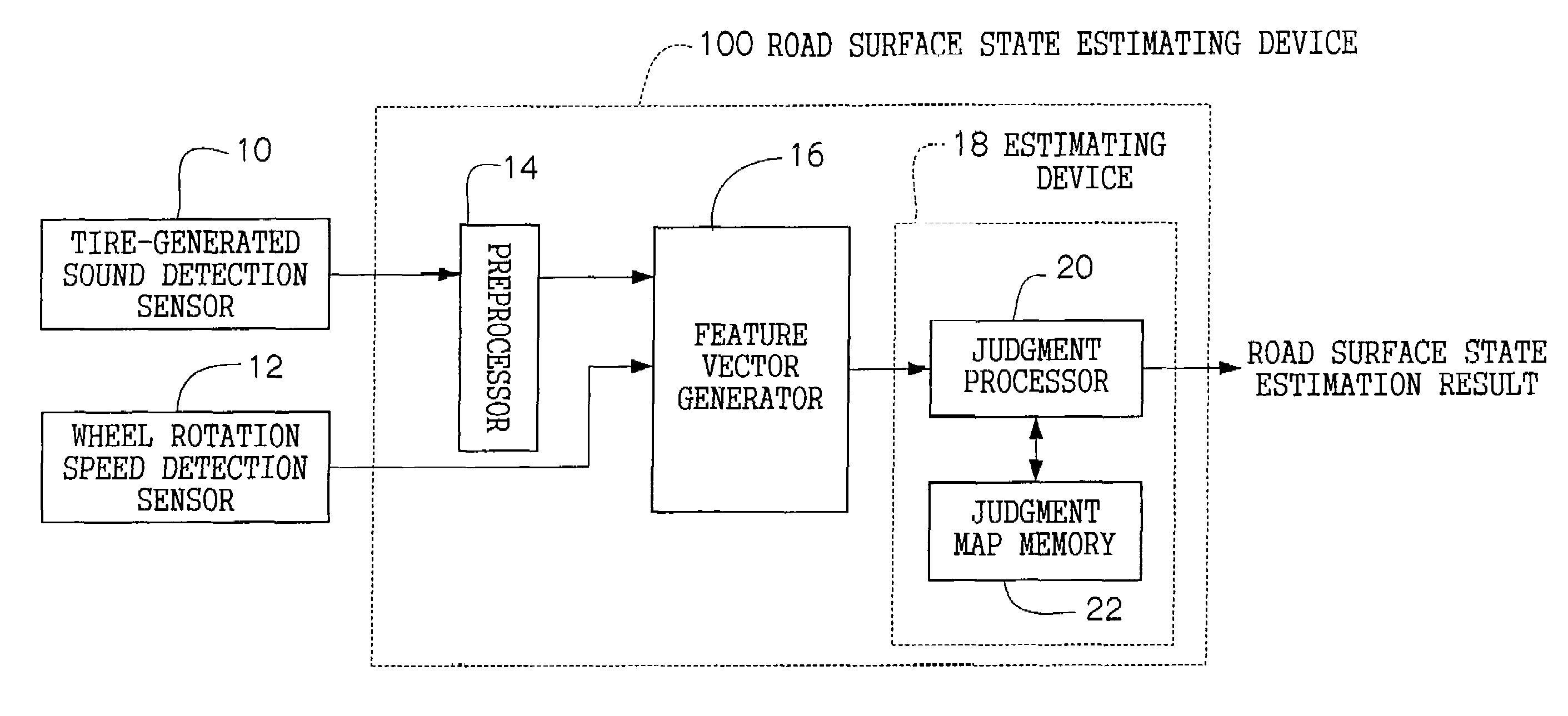
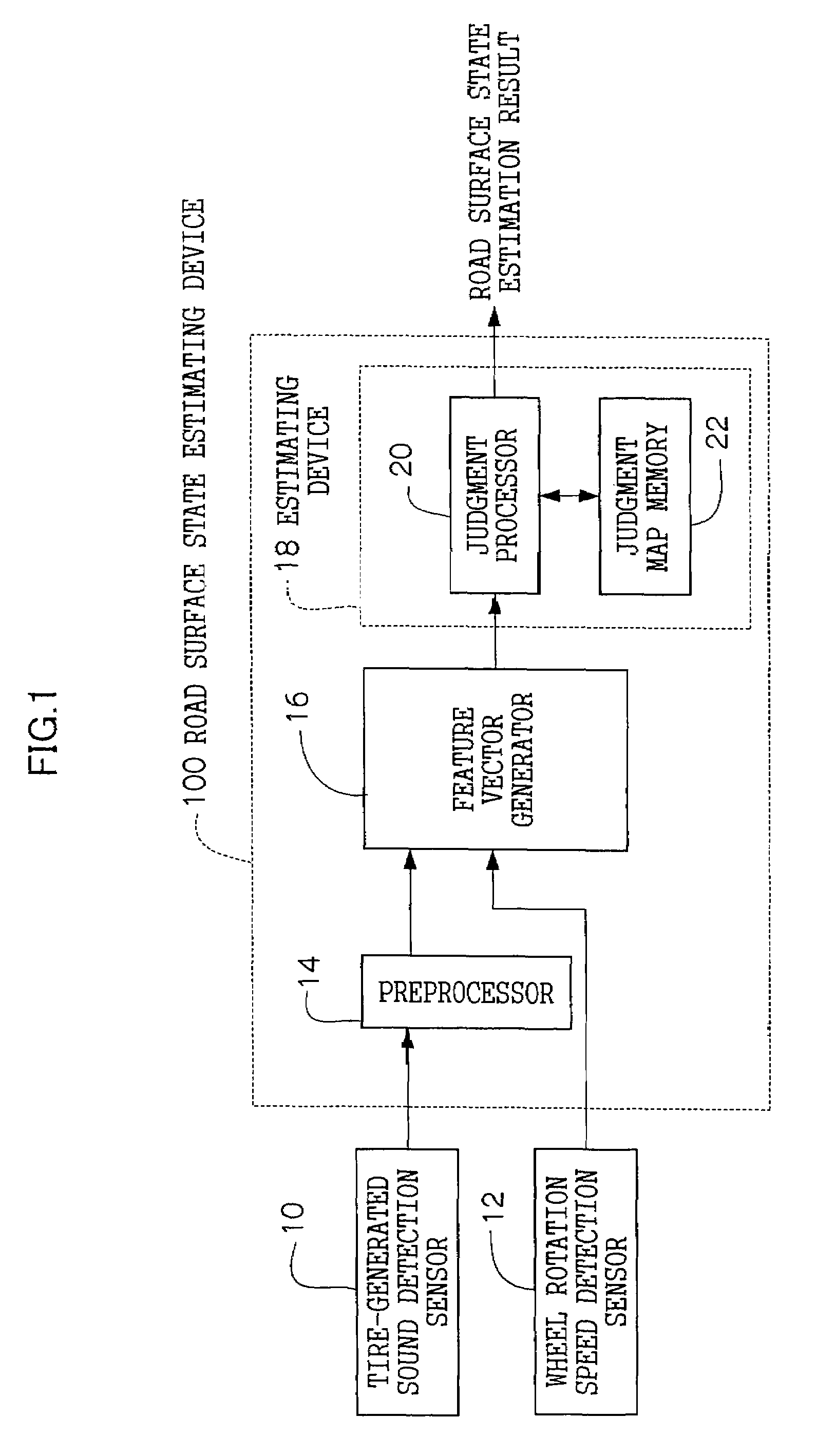
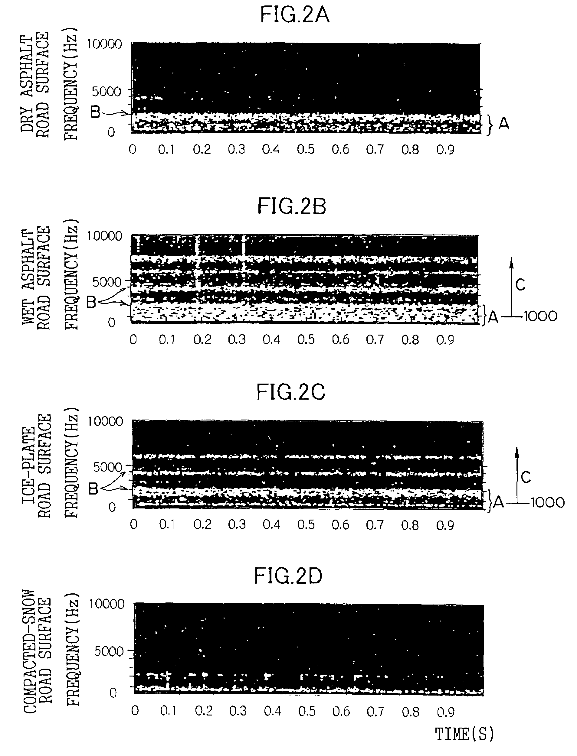
[0018]As described above, at least one feature quantity corresponding to a road surface state and a tire-generated sound source is calculated on the basis of a tire-generated sound instead of handling the tire-generated sound itself, which makes it possible to reduce the amount of information that is necessary to estimate a road surface state. Since a state of a road surface on which the vehicle is running is estimated on the basis of calculated feature quantities and the feature quantities that are stored for respective road surface states and each of which corresponds to a road surface state and a tire-generated sound source, the road surface state can be estimated accurately.
[0072]In view of this, the final road surface friction state estimating device estimates a final road surface friction state on the basis of the road surface state detected by the road surface state detector and the road surface friction state estimated by the road surface friction state estimating device if the judging component judges that the road surface friction state detected by the road surface friction state estimating device falls within the road surface friction state range corresponding to the road surface state detected by the road surface state detector. Therefore, a road surface friction state can be estimated accurately.

Problems solved by technology

However, in the former apparatus, since a tire-generated sound is FFT-analyzed and resulting frequency components are used as inputs, the input frequency components cover a wide frequency range, as a result of which a long calculation time is needed and a considerable number of errors occur.
Therefore, even if these apparatus are mounted on a vehicle actually, it is difficult for them to satisfy requirements.
Therefore, a road surface friction coefficient cannot be estimated accurately if the stored road surface states and feature quantities are incorrect.

Method used


Image

  • Road surface state estimating apparatus, road surface friction state estimating apparatus, road surface state physical quantity calculating apparatus, and road surface state announcing apparatus
  • Road surface state estimating apparatus, road surface friction state estimating apparatus, road surface state physical quantity calculating apparatus, and road surface state announcing apparatus
  • Road surface state estimating apparatus, road surface friction state estimating apparatus, road surface state physical quantity calculating apparatus, and road surface state announcing apparatus

Examples


specific example 1

[0243]The map correction processor 118 stores the following typical feature vectors of forward road surface feature quantities in the μ judgment map memory 112 in advance:

x1=(x11, x12, . . . x1d)

x2=(x21, x22, . . . x2d)[0244]. . .

xn=(xn1, xn2, . . . xnd)

The components xn1, xn2, . . . xnd, etc. are forward road surface feature quantities.

[0245]Further, the correction processor 118 stores the following forward road surface friction coefficients μ that correspond to the above respective feature vectors one to one in the μ judgment map memory 112 in advance:

x1→μ1

x2→μ2

. . .

xn→μn

[0246]Now assume that the forward road surface feature vector at the present time is xa. First, the μ judgment processor 110 calculates distances in the d-dimensional feature space between the feature vector xa and the feature vectors x1, x2, . . . xn that are stored in the μ judgment map 112 and selects a map feature vector having a shortest distance.

[0247]Assume that forward road surface friction coefficients μ ...

specific example 2

[0259]An example in which a map is corrected by the back propagation method using a neural network will be described below.

[0260]Each of the μ judgment processors 110 and 124 is formed by a neural network shown in FIG. 12.

[0261]Inputs x0, . . . , xj, . . . , xd to an input layer K are components of a feature vector, and outputs μ1, . . . , μ1, . . . , μc from an output layer L are components of a vector that indicates a road surface friction coefficient value corresponding to the input feature vector.

[0262]In each of the μ judgment processors 110 and 124, feature vectors of typical road surfaces

x1=(x11, x12, . . . , x1d)

x2=(x21, x22, . . . , x2d)

. . .

xn=(xn1, xn2, . . . , xnd)

and road surface friction coefficients μ1, μ2, . . . , μn corresponding to the above feature vectors one to one are employed as leaning data and teacher data, respectively. The neural network is caused to learn so as to output the teacher data μ1, μ2, . . . , μn in response to the learning data x1, x2, . . . , ...


PUM


Abstract

A tire-generated sound detection sensor detects a tire-generated sound that is generated from a tire while the vehicle is running. A wheel rotation sensor detects a wheel rotation speed. A preprocessor calculates feature quantities corresponding to a road surface state and tire-generated sound sources. A feature vector generator generates a feature vector having, as components, the feature quantities calculated by the preprocessor and the detected wheel rotation speed. A judgment processor estimates a state of a road surface on which the vehicle is running on the basis of the feature vector generated by the feature vector generator and feature vectors that are stored in a judgment map memory so as to be correlated with a plurality of road surface states, respectively, and each of which corresponds to a road surface state and tire-generated sound sources.

Description

CROSS-REFERENCE TO RELATED APPLICATION[0001]This application claims priority under 35USC 119 from Japanese Patent Applications No. 2002-325397 and 2003-353579 the disclosure of which is incorporated by reference herein.BACKGROUND OF THE INVENTION[0002]1. Field of the Invention[0003]The present invention relates to a road surface state estimating apparatus, a road surface friction state estimating apparatus, a road surface state physical quantity calculating apparatus, and a road surface state announcing apparatus. In particular, the invention relates to a road surface state estimating apparatus for estimating a road surface state on the basis of a sound that is generated by a tire while a vehicle is running, road surface luminance information, and other information and a road surface friction state estimating apparatus, a road surface state physical quantity calculating apparatus, and a road surface state announcing apparatus that relate to the above road surface state estimating ap...

Claims


Application Information

Patent Timeline
IPC IPC(8): G06F19/00B60R16/02B60T8/172B60W40/06B60W40/068
CPCB60T8/1725B60T2210/12B60W40/068B60W2420/54
Inventor WATANABE, YOSHITOSHIASANO, KATSUHIROUMENO, TAKAJIASAMI, SHUSUGAI, MASARU
Owner TOYOTA CENT RES & DEV LAB INC
Learn More