
Micro-electromechanical structure resonator frequency adjustment using radiant energy trimming and laser/focused ion beam assisted deposition

a technology of electromechanical structure and frequency adjustment, which is applied in the direction of relays, electrostatic generators/motors, generators/motors, etc., can solve the problems of large overall system size, large discrete crystals and saw generating devices, and increased production costs and installation costs

Inactive Publication Date: 2007-07-17
INTEL CORP
View PDF44 Cites 18 Cited by
  • Summary
  • Abstract
  • Description
  • Claims
  • Application Information

AI Technical Summary

Benefits of technology

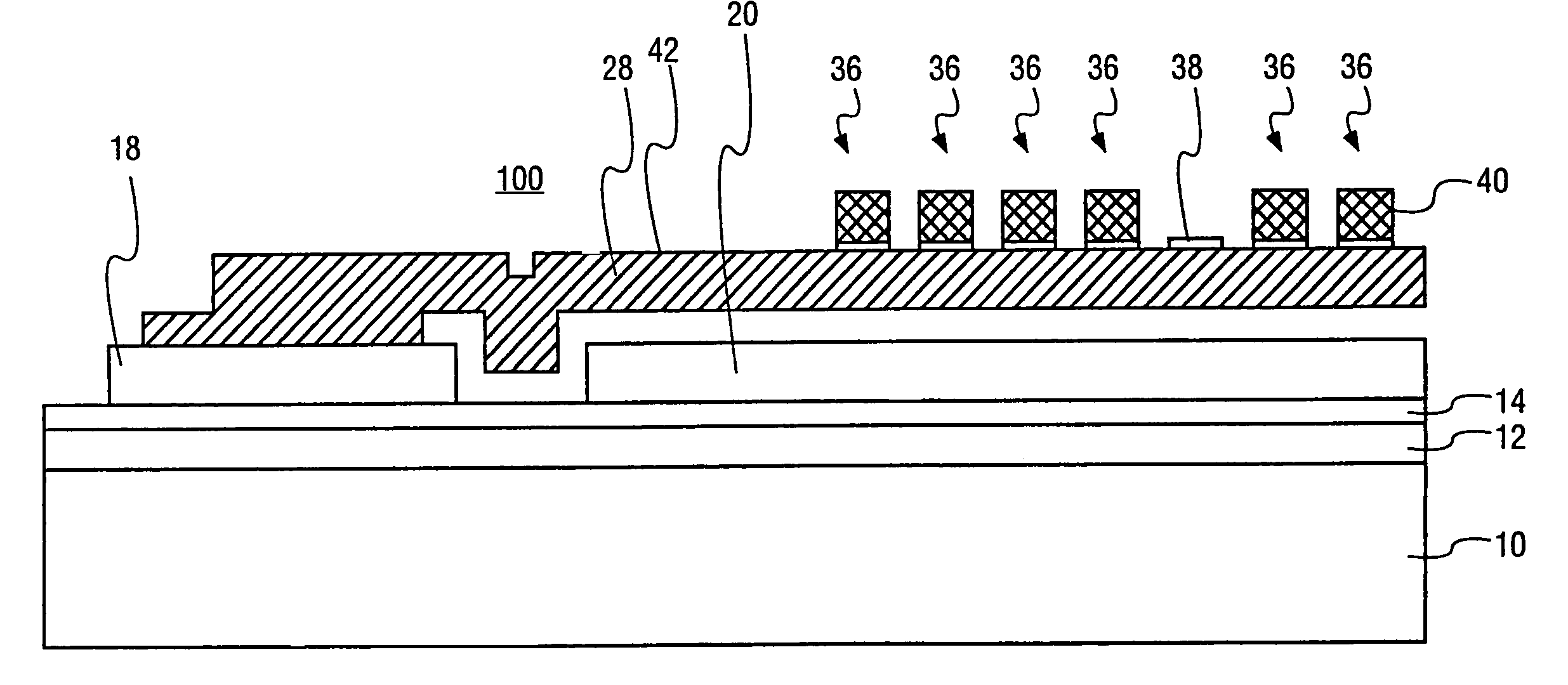
The present invention relates to a method for fabricating a high frequency beam resonator, which is a micro electromechanical structure (MEMS) resonator that can be used for signal filtering and signal generating purposes. The invention addresses the problems in prior art where discrete crystals and SAW devices were larger and more expensive to package and process variations could result in yield loss. The invention provides a solution for miniaturizing the resonator and adjusting its frequency through further processing. The invention also includes a process flow chart for manufacturing the resonator. The resonator can be used in various applications such as signal filtering and signal generating.

Problems solved by technology

As miniaturization of devices progresses, the discrete crystals and SAW generating devices become relatively larger and therefore much more difficult to package.
For example, discrete devices limit the size of the overall system to larger configurations and they are more expensive to produce and to install.
Once a resonator is fabricated, process variances may cause a given resonator to have a frequency that is not within preferred range for a given application.
For such out-of-range resonators, if another use therefor cannot be found, the resonator must be discarded as a yield loss.

Method used


Image

  • Micro-electromechanical structure resonator frequency adjustment using radiant energy trimming and laser/focused ion beam assisted deposition
  • Micro-electromechanical structure resonator frequency adjustment using radiant energy trimming and laser/focused ion beam assisted deposition
  • Micro-electromechanical structure resonator frequency adjustment using radiant energy trimming and laser/focused ion beam assisted deposition

Examples


Embodiment Construction

[0025]The following description includes terms, such as upper, lower, first, second, etc. that are used for descriptive purposes only and are not to be construed as limiting. The embodiments of an apparatus or article of the present invention described herein can be manufactured, used, or shipped in a number of positions and orientation.

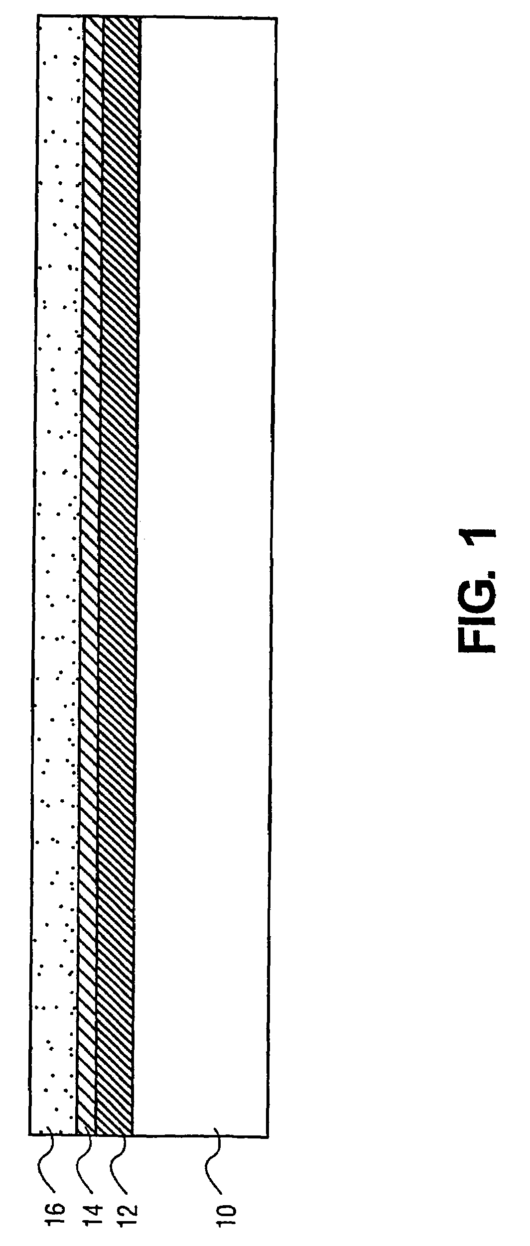
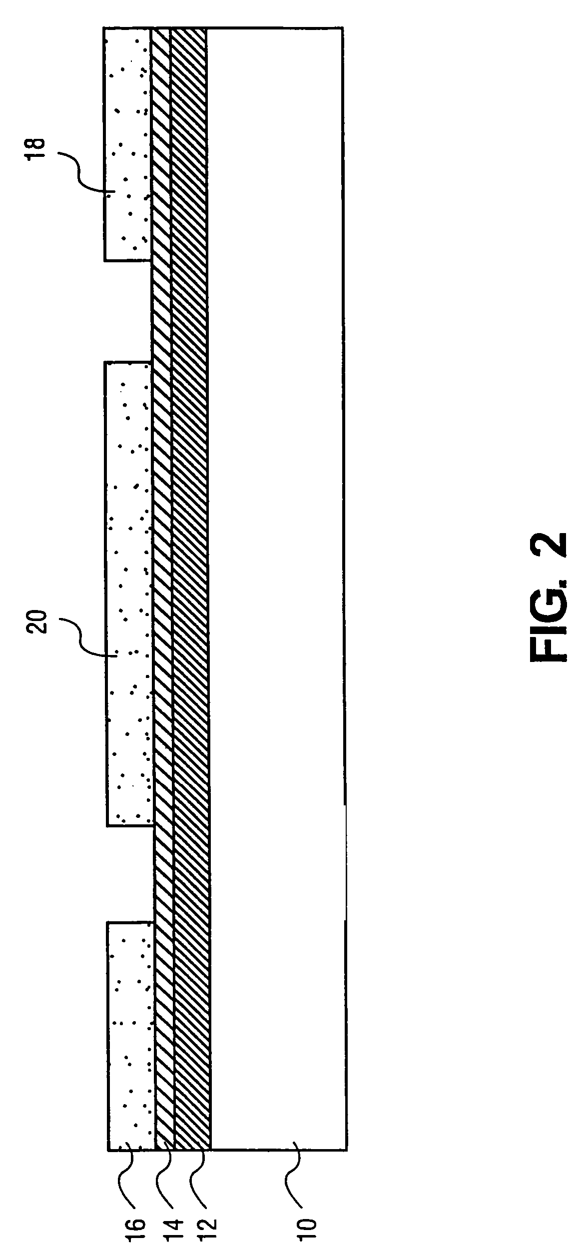
[0026]Reference will now be made to the drawings wherein like structures will be provided with like reference designations. In order to show the structures of the present invention most clearly, the drawings included herein are diagrammatic representations of integrated circuit structures. Thus, the actual appearance of the fabricated structures, for example in a photomicrograph, may appear different while still incorporating the essential structures of the present invention. Moreover, the drawings show only the structures necessary to understand the present invention. Additional structures known in the art have not been included to maintain the clar...


PUM

PropertyMeasurementUnit
temperatureaaaaaaaaaa
grain sizeaaaaaaaaaa
massaaaaaaaaaa

Abstract

The invention relates to a microbeam oscillator. Tuning of the oscillator is carried out by addition or subtraction of material to an oscillator member in order to change the mass of the oscillator member.

Description

CROSS-REFERENCE TO RELATED APPLICATIONS[0001]This application is a divisional of U.S. patent application Ser. No. 09 / 738,118, filed on Dec. 15, 2000, and claims priority therefrom under 35 U.S.C. § 120. The priority application is currently pending.BACKGROUND OF THE INVENTION[0002]1. Field of the Invention[0003]The present invention relates generally to micro electromechanical structure (MEMS) fabrication and, more specifically, the present invention relates to the fabrication of a high frequency beam resonator. In particular, the present invention relates to frequency adjustment of the high frequency beam resonator.[0004]2. Description of Related Art[0005]As microelectronic technology progresses, the need has arisen for smaller and higher frequency resonators for both signal filtering and signal generating purposes among others. The prior state of the art used discrete crystals or devices that generate a surface acoustical wave (SAW) for their desired functions. As miniaturization ...

Claims


Application Information

Patent Timeline
Patent Type & Authority Patents(United States)
IPC IPC(8): H01L41/08H10N30/00B81B3/00H02N2/00H03H9/02H03H9/24
CPCB81C1/0015H03H9/2405H03H9/02393B81B2201/0271B81C2201/053Y10T29/49105H03H2009/02511Y10T29/4916
Inventor MA, QINGCHENG, PENGRAO, VALLURI
Owner INTEL CORP
Learn More