
Gantry-type XY stage

a gantry-type, stage technology, applied in the direction of photomechanical equipment, instruments, manufacturing tools, etc., can solve the problems of aforementioned prior art technique having problems, image wobble, and inability to ensure a sufficient shape accuracy, so as to reduce the effect of wobbl

Inactive Publication Date: 2007-07-03
LASERFRONT TECH
View PDF10 Cites 21 Cited by
  • Summary
  • Abstract
  • Description
  • Claims
  • Application Information

AI Technical Summary

Benefits of technology

"The present invention is about a gantry-type XY stage that reduces wobbles associated with movements of a gantry section. The invention uses a granite plate, a pair of posts made of a composite material having a high rigidity, a beam made of a composite material having a high rigidity, and a movement base. By using composite materials with a high vibration absorbency and damping effect, the invention can limit the wobbles of the posts and beam. The beam is made hollow to reduce material cost and prevent deformation over time. A supporting member made of a composite material counteracts deflection and twisting, and the distance between the top of the beam and the bottoms of the posts can be made more consistent. The gantry-type XY stage can be used in various applications such as defect testing and laser repair."

Problems solved by technology

This is because the gantry section formed of forging, for example, rolled steel would inevitably suffer from bowing in the rolling direction, thereby failing to ensure a sufficient shape accuracy.
However, the aforementioned prior art technique has problems as shown below.
This causes wobbles in an image for observing a liquid crystal display to be repaired.
Then, since the liquid crystal display cannot be processed for repair until the wobbles comes to end, causing a longer processing time per liquid crystal display.
When the gantry section is moved at low speeds, the occurrence of wobbles can be limited, but the processing time per liquid crystal display will become longer after all.

Method used


Image

  • Gantry-type XY stage
  • Gantry-type XY stage
  • Gantry-type XY stage

Examples


Embodiment Construction

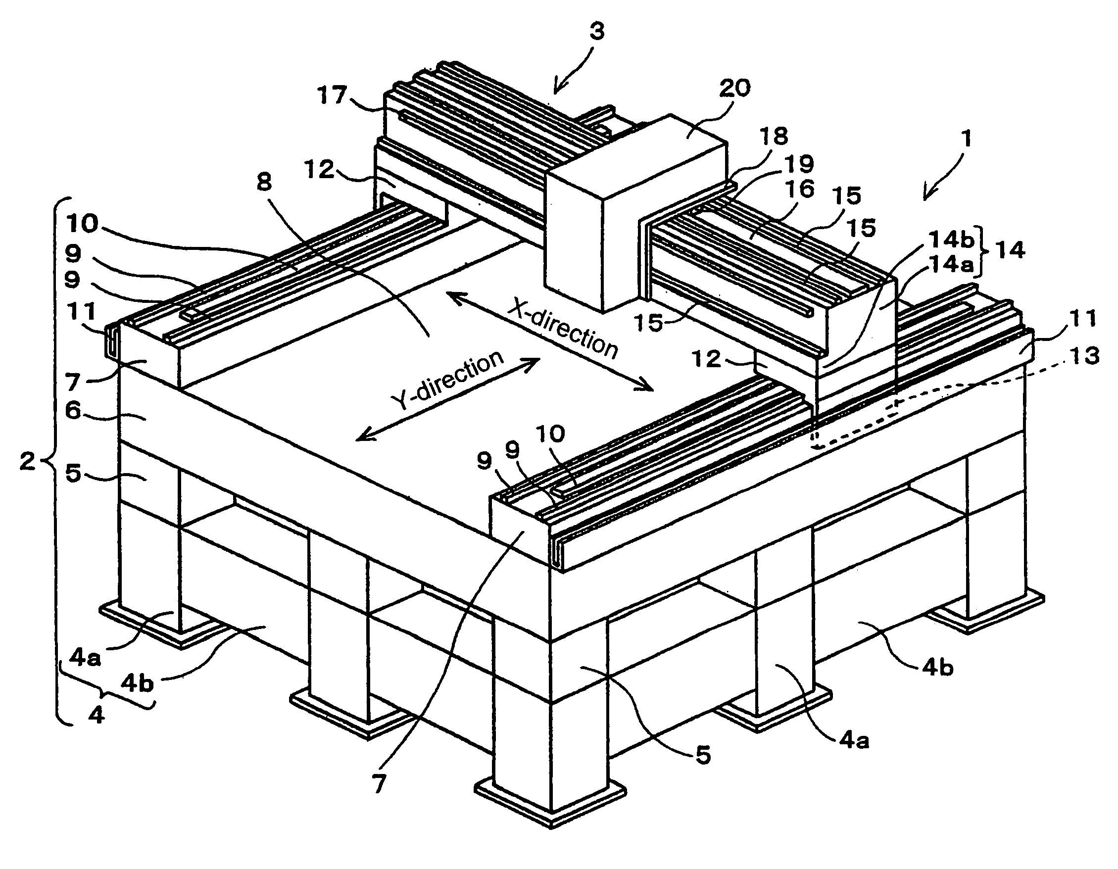
[0022]A gantry-type XY stage according to an embodiment of the present invention is installed in a laser repair apparatus for correcting TFT substrates of liquid crystal displays for defects during manufacturing. As illustrated in FIG. 1, gantry-type XY stage 1 according to the embodiment is provided with base section 2, which is a stationary portion, and gantry section 3, which is a movable portion, carried on base section 2.

[0023]In base section 2, pedestal 4 is provided for supporting entire gantry-type XY stage 1. Pedestal 4 comprises nine posts 4a arranged at equal intervals in three rows and three columns; and beams 4b for coupling adjacent posts 4a to each other. Posts 4a and beams 4b are formed, for example, of rectangular steel pipes for general structures described in JIS (Japanese Industrial Standards) G3466. Also, each of posts 4a of pedestal 4 is provided thereon with each vibration isolating mount 5. In other words, a total of nine vibration isolating mounts 5 are prov...


PUM

PropertyMeasurementUnit
Young's modulusaaaaaaaaaa

Abstract

Nine vibration isolating mounts are disposed on a pedestal, and a granite plate is placed thereon. A pair of guide bases are disposed on the granite plate, and disposed thereon are a pair of posts made of CFRP for movements in a Y-direction relative to the granite plate. A beam made of CFRP is extended between the pair of posts. Further, a movement base is disposed for movement in an X-direction relative to the beam, and a laser optical unit is mounted on the movement base.

Description

BACKGROUND OF THE INVENTION[0001]1. Field of the Invention[0002]The present invention relates to a gantry-type XY stage for use in an apparatus which performs local processing on a plane structure, and more particularly, to a gantry-type XY stage for use in a laser repair apparatus for liquid crystal displays, a laser repair apparatus for liquid crystal masks, a patterning apparatus for solar cell panels, a defect inspection apparatus for liquid crystal displays, a defect inspection apparatus for semiconductor devices, and the like.[0003]2. Description of the Related Art[0004]A laser repair apparatus for correcting manufacturing defects on a TFT (Thin Film Transistor) substrate of a liquid crystal display is provided with a gantry-type XY stage as a main component unit. The gantry-type XY stage is comprised of a base section which is a stationary portion, and a gantry section which is a movable portion disposed on the base section. The base section is provided with a granite plate, ...

Claims


Application Information

Patent Timeline
Patent Type & Authority Patents(United States)
IPC IPC(8): G01R31/02B23Q1/01G01N21/84G02B7/00G03F7/20H01L21/68
CPCB23K26/0876G02B7/005G03F7/70716G02F1/1309H01L21/6715
Inventor IWANAGA, YASUSHIMITOBE, KAZUHIKO
Owner LASERFRONT TECH
Learn More