Electronic ballast with adaptive lamp preheat and ignition

a technology of electronic ballasts and lamp preheating, applied in the field of electronic ballasts, can solve the problems of increasing core losses in addition to conduction losses, affecting the ability of electronic ballasts to work properly, etc., to achieve the effect of improving the ability of electronic ballasts

Inactive Publication Date: 2007-07-03
UNIVERSAL LIGHTING TECHNOLOGIES
View PDF25 Cites 22 Cited by
  • Summary
  • Abstract
  • Description
  • Claims
  • Application Information

AI Technical Summary

Benefits of technology

[0020]To improve the ability of electronic ballasts to provide optimum inverter frequencies during lamp preheat and ignition, one object of the present invention is to detect the unloaded frequency response of the inverter resonant tank during or before the preheat and / or strike of the lamp. This information is used by a microcontroller operating the ballast to adapt the inverter frequency during lamp preheat and ignition phases. The microcontroller can select the optimum frequency to strike the lamp with minimum stress on the components, and make it possible to use minimum value of parallel resonant capacitor.
[0022]During normal operation, the efficiency of the ballast is improved due to lower circulation current and smaller size of the resonant inductor. This allows the ballast to consistently preheat and strike the lamp with optimum frequency, taking into account variations in the values of the resonant inductor, resonant capacitor, and, in particular, the stray reactance introduced by a long external conduit connecting the ballast to the lamp. Accordingly, the resonant capacitor and magnetic core of the resonant inductor can be designed to be smaller. A smaller resonant capacitor results in a lower circulation current and lower losses in the inverter transistors inductors. This, in turn, allows the preheat frequency to be higher, so that the filament capacitor can be smaller. Consequently, the steady state losses on the lamp filament are reduced, and the pin current limitation of the lamp is easier to satisfy. The ballast is less expensive, runs cooler, performs better, and is easier to design, for instant start, program start, or dimming ballasts.

Problems solved by technology

These three inverter frequencies are plotted on FIG. 2 as points A, B, and C. Although there are limitations to programming these functions using different resistor and capacitor values, analog controllers are popular because of their low cost.
On the other hand, because the flux density of the core of the inductor is proportional to IL, a higher IL increases core losses in addition to the conduction loss.
Thus, a high value Cp requires Lr to store more energy, which means either more losses or a larger core size.
This requires a larger air gap with higher fringing losses, more winding turns with more conduction losses, and, in some cases, a bigger core with more core losses and higher cost.
Using a low value of Cp with traditional analog control circuits is not practical because of the stray capacitance associated with the connection between the ballast and the fixture and with the fixture itself.
This measurement confirms that stray capacitance can result in insufficient striking voltage.
However, with T5HO lamps which run at much higher currents (440 mA instead of 180 ma) the permissible pulse duration is only about 1 millisecond and with current technology it is not possible to perform a frequency sweep during this time interval.
As the result, the filament preheat is not sufficient and the life span of the lamp is reduced.
There are several obvious disadvantages to this solution.
There can be more than 100 hard switching cycles when no lamp is connected, which is hazardous to the ballast.
However, a higher resonant capacitance establishes a preheat frequency that cannot be much higher than the normal running frequency.
As a result, the filament capacitor does not provide much attenuation to the filament current at normal operating frequency when under conditions when the preheat to the filaments is sufficient.
The losses on the filaments are relatively high.
In either program start or instant start ballasts, a high value of the resonant capacitor results in high circulation current at steady state, which means higher conduction losses in the transistors and inductor.

Method used


Image

  • Electronic ballast with adaptive lamp preheat and ignition
  • Electronic ballast with adaptive lamp preheat and ignition
  • Electronic ballast with adaptive lamp preheat and ignition

Examples


Embodiment Construction

[0032]The microcontroller has been used in the prior art to control certain functions in an electronic ballast, such as lamp detection, re-lamping, and multiple striking. However, prior art use of microcontrollers has not resulted in improvement of inverter performance during the lamp preheat and ignition phases.

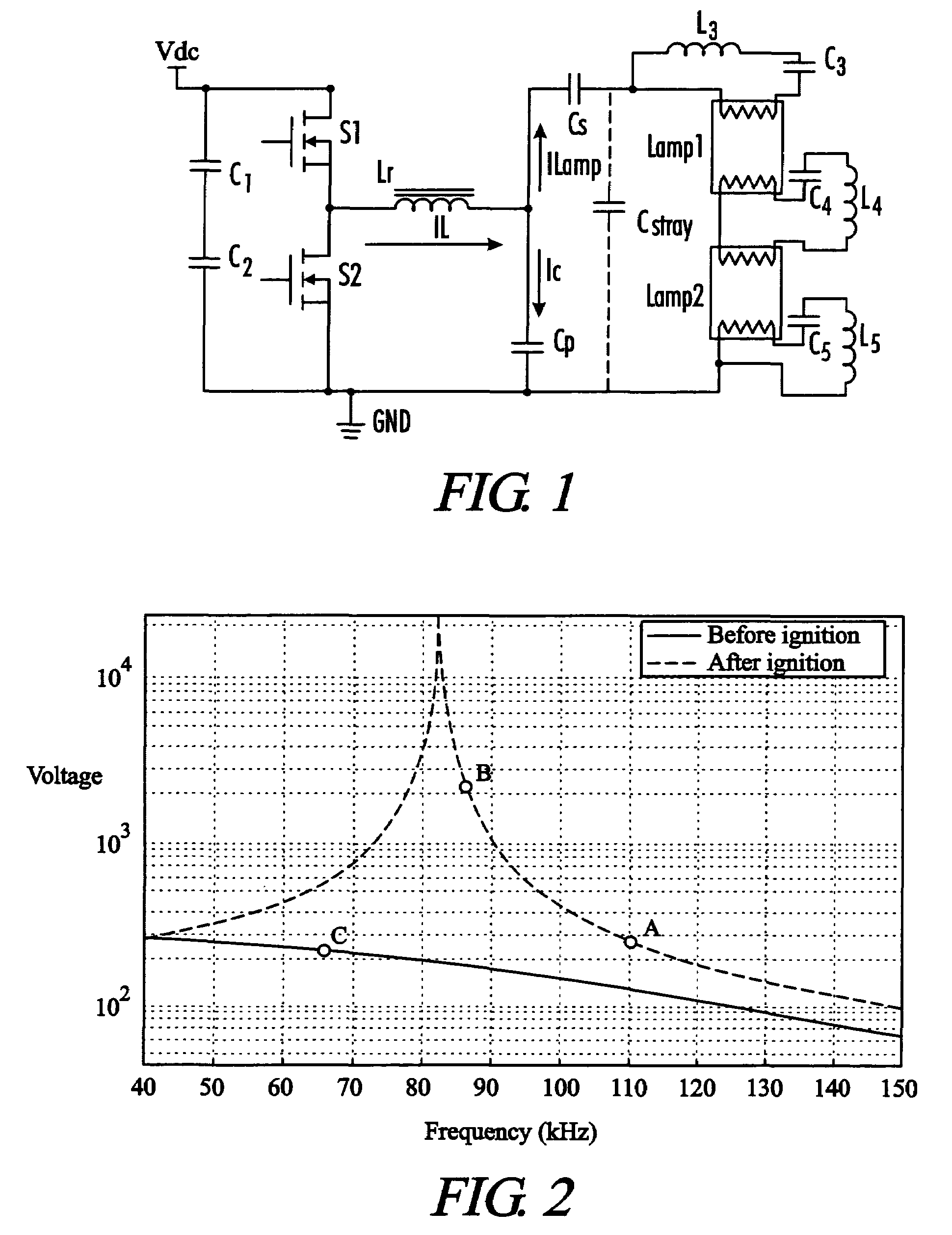
[0033]In coventional microcontroller-based electronic ballasts, the microcontroller generates the frequency signal for the ballast. For example, in the ballast of FIG. 1, the frequency of the FET (S1 and S2) gate signals is controlled by the microcontroller (not shown). In the present invention as shown in FIG. 8, the microcontroller U1 also samples the lamp voltage, which is proportional to the voltage across the resonant capacitor Cp. This sampling is done using a simple analog filter circuit comprising resistors and capacitors. The output of the filter circuit is coupled to an analog input pin on microcontroller U1. An A / D converted integral to microcontroller U1 converts...


PUM


Abstract

An electronic ballast includes a microcontroller with software to provide an adaptive lamp preheat and ignition operation. The microcontroller commands a test frequency from the inverter and detects the frequency response of the resonant output circuit by measuring the voltage across the resonant capacitor. The measured voltages are compared to one or more reference voltages as the frequency is varied to select the optimal inverter frequency. An algorithm or look-up table is used to set the inverter frequencies for the lamp preheat and ignition phases.

Description

CROSS-REFERENCES TO RELATED APPLICATIONS[0001]This application is a Non-Provisional Utility application which claims benefit of co-pending U.S. Provisional Patent Application Ser. No. 60 / 526,639 filed Dec. 3, 2003, entitled “Adaptive Preheat and Strike for Microcontroller Based Ballast” which is hereby incorporated by reference.STATEMENT REGARDING FEDERALLY SPONSORED RESEARCH OR DEVELOPMENT[0002]Not ApplicableREFERENCE TO SEQUENCE LISTING OR COMPUTER PROGRAM LISTING APPENDIX[0003]Not ApplicableBACKGROUND OF THE INVENTION[0004]The present invention relates generally to electronic ballasts used to operate gas discharge lamps. More particularly, this invention pertains to circuits and methods used to control the preheating and ignition (“striking”) of a gas discharge lamp by an electronic ballast having a resonant tank output.[0005]Conventional electronic ballasts typically combine a power factor correction (PFC) stage with a high frequency resonant inverter to preheat, strike and driv...

Claims


Application Information

Patent Timeline
Patent Type & Authority Patents(United States)
IPC IPC(8): H05B37/02H05B41/00H05B41/02H05B41/14H05B41/295H05B41/36
CPCH05B41/295Y10S315/05
Inventor RADZINSKI, CHRISTOPHERDERNOVSEK, JOHN JAYYU, QINGHONG
Owner UNIVERSAL LIGHTING TECHNOLOGIES
Why Eureka
Try Eureka