
Architecture for an application framework

an application framework and architecture technology, applied in software design, data processing applications, instruments, etc., can solve problems such as errors and inefficiency

Inactive Publication Date: 2007-06-26
MIND FUSION LLC
View PDF15 Cites 55 Cited by
  • Summary
  • Abstract
  • Description
  • Claims
  • Application Information

AI Technical Summary

Benefits of technology

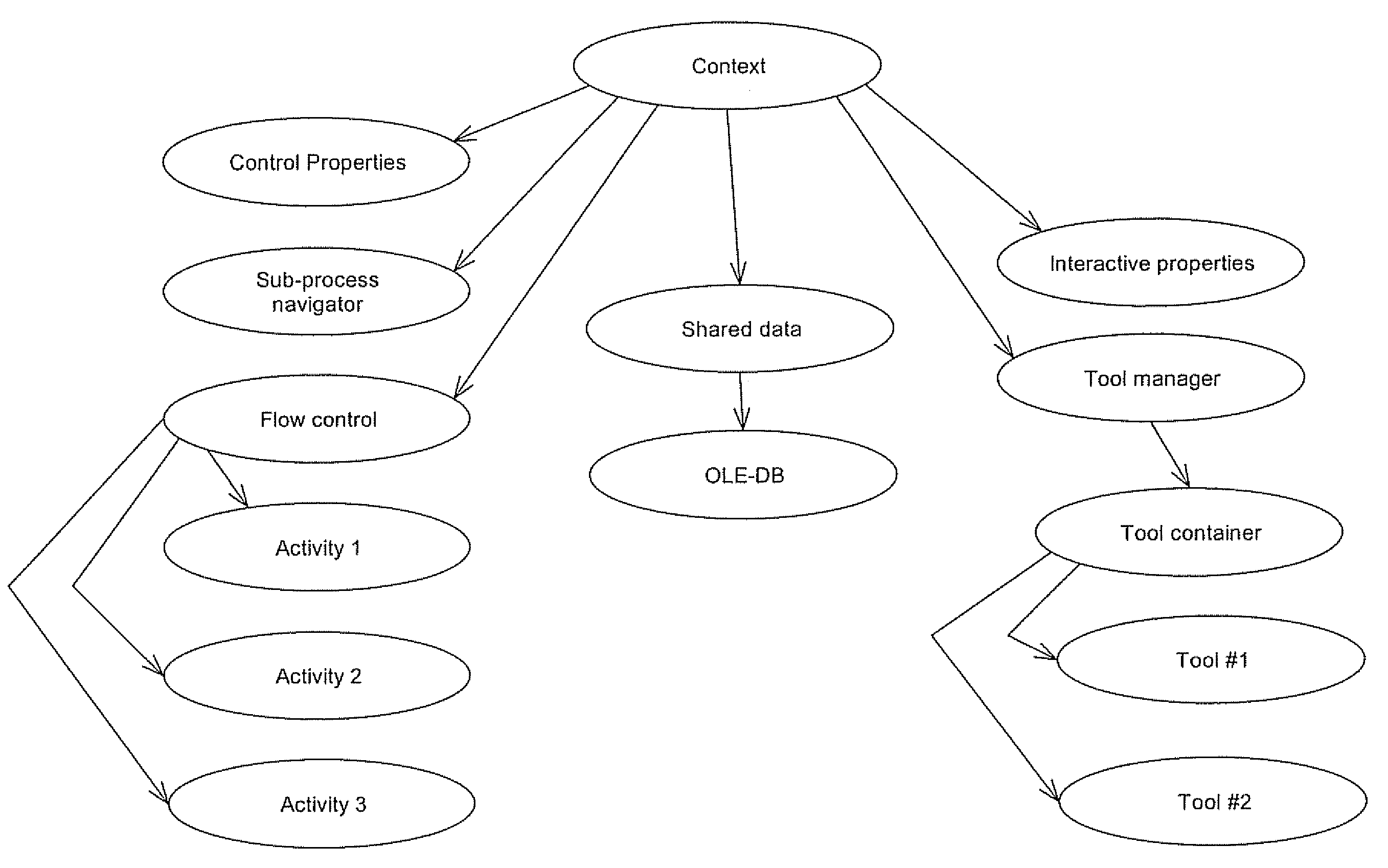
[0012]In addition a “process definition” is the “program”, or processing steps that comprise a process. This must be retrieved from persistent storage before a process can be started, so that the activities, tools and control logic can be instantiated for the requested process. A “process instance” refers to a running version of a process—i.e., the process definition plus the data and state information used while it is running. The framework can support multiple process instances—to the user will simply look like different contexts which can be using different data and processing, and which can be switched to be the foreground task.
[0013]In order to the framework to support reuse of activities from different sources, it is desirable to define user interface model. Here the approach taken is direct mapping of each of the above levels to a region on the UI, with the addition of support for “tools”. The largest part of the UI is assigned for the current activity—this is called the “work area” here.

Problems solved by technology

Thus the user has to relearn new procedures resulting in errors and inefficiency.

Method used


Image

  • Architecture for an application framework
  • Architecture for an application framework
  • Architecture for an application framework

Examples


Embodiment Construction

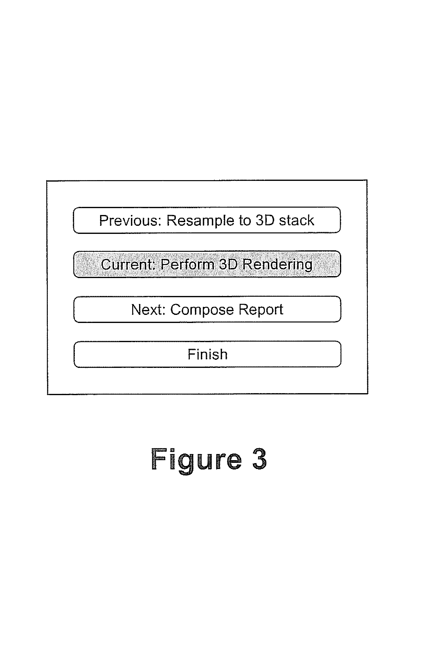
[0027]Referring to FIG. 1 an overview of the default user interface associated with an “application” which uses this framework is shown. The interface defines four areas namely work area, process selector, sub-process navigator and tools area. The default configuration has the work area on the right, with the 3 other regions stacked on the left in a single column

[0028]This work area is typically used for the display of images, or any secondary user interface that is required by an activity. The current activity owns the work area. The framework arbitrates the ownership of the work area. The contents of the work area may be preserved between activities—description of the contents of the area can be shared using properties stored in the “shared data context”.

[0029]Although the contents of this area are “arbitrary”, it is likely that activities will need to share information about the contents. For example, an activity that allows some manipulation of the displayed images would need to...


PUM


Abstract

The present invention discloses a framework for monitoring workflow within an application having multiple levels of functionality, the framework being capable of combining a plurality of components from different sources and comprising a process level for selecting a set of defined process steps to be applied to a data set associated with a set of activities, a sub-process level including an aggregation of selected activities from the set of activities and facilitating navigation between the selected activities, and an activity level wherein an activity's property in the data set is modified as a result of the applied processing of the activity level to produce an output data set.

Description

[0001]This application in a continuation of PCT patent application No. PCT / CA98 / 01099, filed on Dec. 1, 1998, which is a continuation-in-part of U.S. Ser. No. 08 / 982,280, filed on Dec. 1, 1997 now abandoned.BACKGROUND OF THE INVENTION[0002]In an application domain such as in medical care, tasks being performed in a hospital for example, are cross departmental and involve several people, each with a different role. These coordinated activities are typically referred to as “Workflow”, with an example being the processing that occurs as a patient moves through the hospital “system”. The first step is “admitting”, which may be followed by an examination and then detailed lab work and imaging. This is followed by a review of the information with recommendations for further tests, or treatment. There are various tools that operate in this enterprise—wide workflow. For example in the imaging part of this process there are specific software tools that are required for the imaging (scanner c...

Claims


Application Information

Patent Timeline
IPC IPC(8): G06F3/00G06F15/16G06F3/048G06F3/0485G06F3/0488G06F9/44G06Q50/00
CPCG06F8/20
Inventor MENHARDT, WIDOHEFFERNAN, PATRICK
Owner MIND FUSION LLC
Learn More