
System and method for controlling an engine in a vehicle

a technology of engine control and vehicle, applied in the direction of external condition input parameters, gas pressure propulsion mounting, driver input parameters, etc., can solve the problems of affecting passenger comfort and convenience, affecting the temperature of the windshield, and affecting the speed of the engine, so as to facilitate a faster heat transfer rate, increase the temperature of combustion within the engine, and more quickly heat the passenger compartment

Inactive Publication Date: 2007-06-26
FORD GLOBAL TECH LLC
View PDF11 Cites 4 Cited by
  • Summary
  • Abstract
  • Description
  • Claims
  • Application Information

AI Technical Summary

Benefits of technology

This approach enables quicker heating of the passenger compartment and catalyst, balancing heat transfer for both passenger comfort and emission reduction without compromising engine performance.

Problems solved by technology

One consequence of having a smaller engine in a vehicle is that it may take longer for the vehicle passenger compartment to get warm.
This can affect passenger comfort and convenience, in that it may also take longer for a windshield to defrost.
One limitation of the method described in Foster, is that it does not take advantage of selective use of a charge motion control valve.
The opening of a charge motion control valve also decreases the turbulence of the intake air entering the engine, however, which can counter the effects of the increased amount of air, and lead to an increase in the combustion temperature.
Another situation that can undesirably increase the time it takes to heat a passenger compartment is execution of a control logic configured to quickly heat a catalyst after the engine is started.
Such a control logic may be used to reduce undesirable exhaust emissions, but may have the unintended effect of making less heat available to the passenger compartment.
This causes unburned fuel that is exhausted from the engine to be combusted at or near the catalyst itself.
Therefore, merely retarding spark timing, and in particular retarding it past top dead center (TDC), can be at odds with quickly heating a vehicle passenger compartment.

Method used


Image

  • System and method for controlling an engine in a vehicle
  • System and method for controlling an engine in a vehicle
  • System and method for controlling an engine in a vehicle

Examples


Embodiment Construction

)

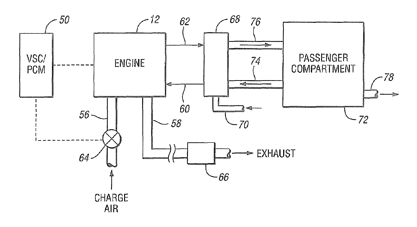
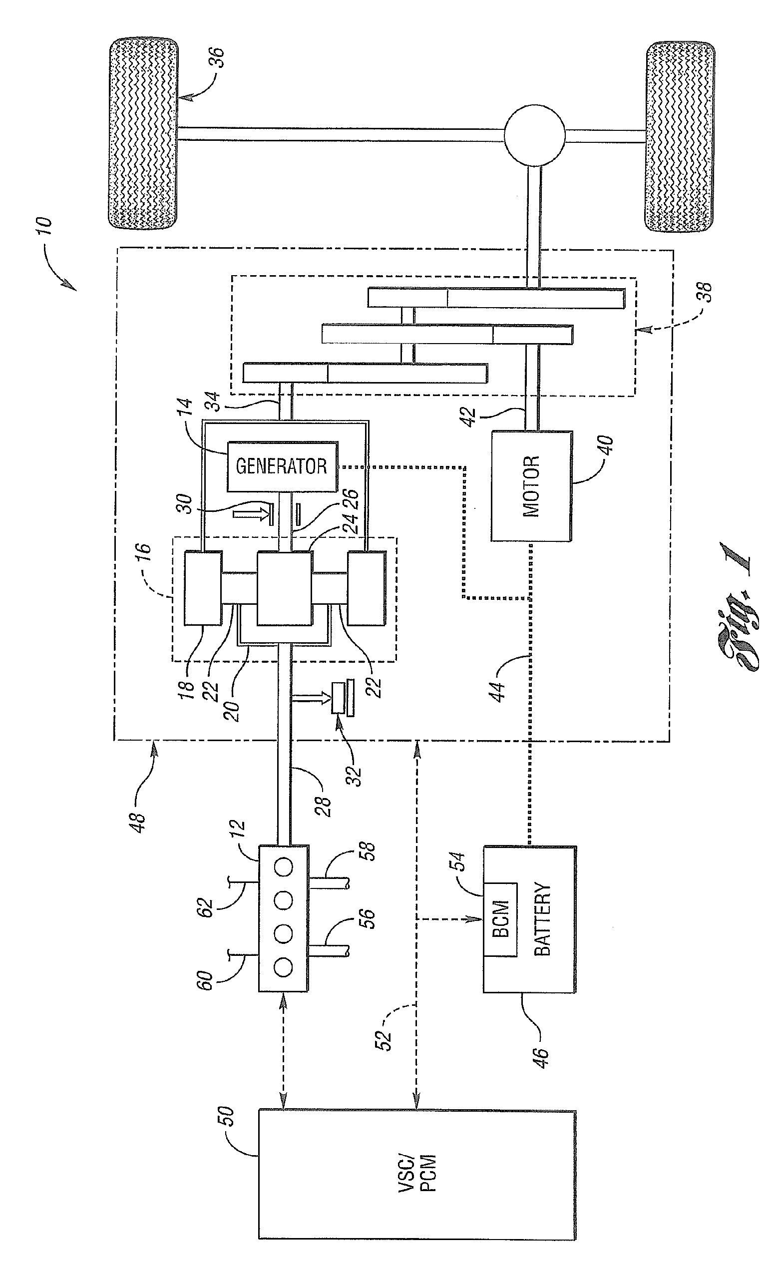
[0017]FIG. 1 shows a schematic representation of a vehicle 10 in accordance with one embodiment of the present invention. The vehicle 10 includes an engine 12 and an electric machine, or generator 14. The engine 12 and the generator 14 are connected through a power transfer unit, which in this embodiment is a planetary gear set 16. Of course, other types of power transfer units, including other gear sets and transmissions, may be used to connect the engine 12 to the generator 14. The planetary gear set includes a ring gear 18, a carrier 20, planet gears 22, and a sun gear 24.

[0018]The generator 14 can also be used as a motor, outputting torque to a shaft 26 connected to the sun gear 24. Similarly, the engine 12 outputs torque to a shaft 28 connected to the carrier 20. A brake 30 is provided for stopping rotation of the shaft 26, thereby locking the sun gear 24 in place. Because this configuration allows torque to be transferred from the generator 14 to the engine 12, a one-way clut...


PUM


Abstract

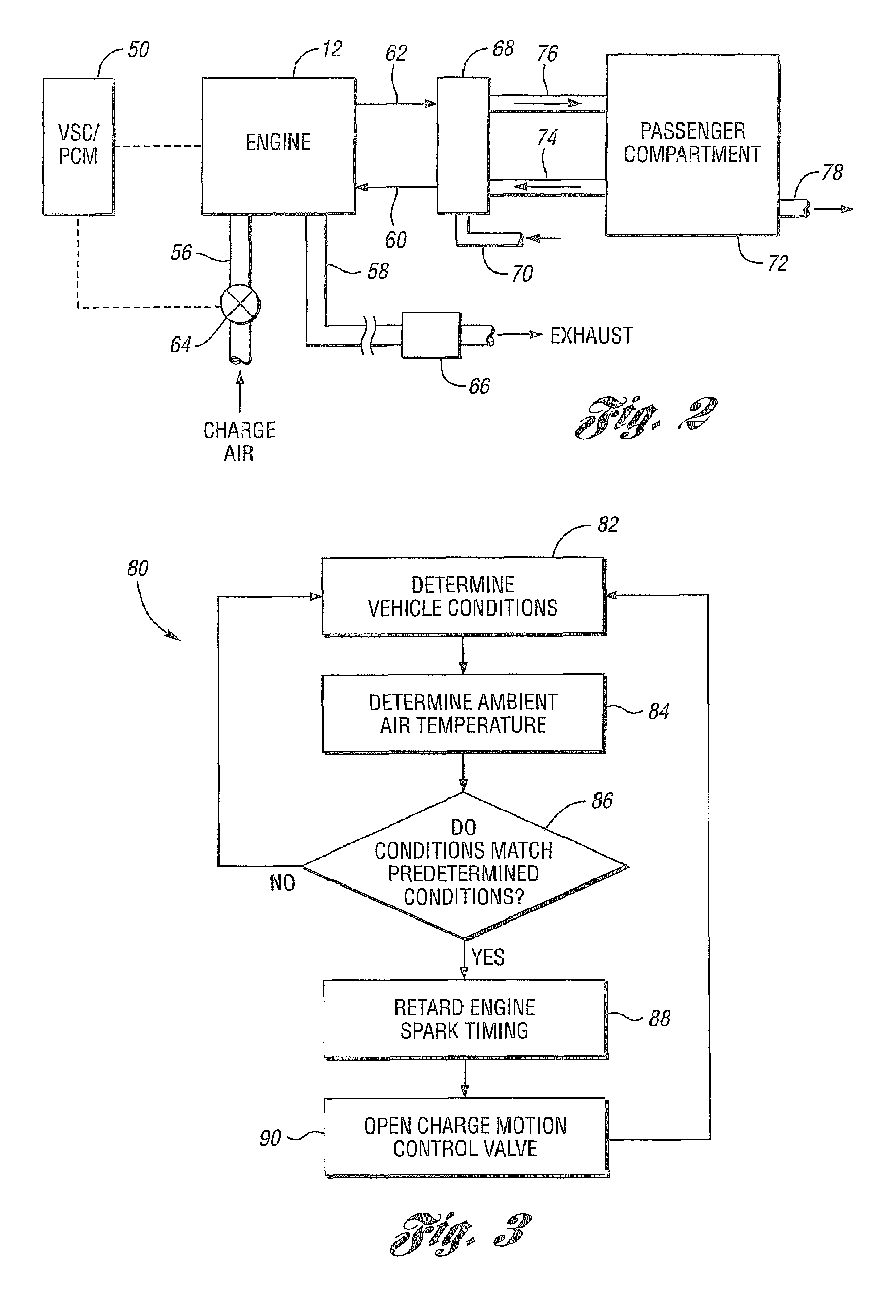
A system and method for controlling an engine in a vehicle to facilitate heat transfer to a passenger compartment is provided. A number of conditions are examined, and if it is found that one or more of these conditions matches a corresponding predetermined condition, the spark timing of the engine is retarded. In addition, a charge motion control valve is opened, thereby increasing the amount, and reducing the turbulence, of the air entering the engine. This facilitates hotter combustion within the engine, and therefore faster heat transfer to the vehicle passenger compartment.

Description

BACKGROUND OF THE INVENTION[0001]1. Field of the Invention[0002]The present invention relates to a system and method for controlling an engine in a vehicle.[0003]2. Background Art[0004]The development of hybrid electric vehicles (HEV's) has provided a way to reduce exhaust emissions and improve fuel economy by reducing the amount of time an engine is running. In addition, because HEV's are equipped with electric motors, the size of the engine can be reduced. Even in some conventional vehicles, engines may be smaller today than in comparable predecessor vehicles, since advances in engine technology have provided increases in engine output power.[0005]One consequence of having a smaller engine in a vehicle is that it may take longer for the vehicle passenger compartment to get warm. This can affect passenger comfort and convenience, in that it may also take longer for a windshield to defrost. One attempt to address this issue is described in U.S. Patent Application Publication No. 200...

Claims


Application Information

Patent Timeline
Patent Type & Authority Patents(United States)
IPC IPC(8): G01F17/00F02D43/00B60K6/365B60K6/445
CPCB60K6/445B60W10/06F02D37/02F02D41/068F02P5/04F02P5/14B60K6/365B60K1/02Y10T477/68B60L2240/445B60L2240/486B60W20/00B60W2510/0676B60W2510/068B60W2540/16B60W2550/12B60W2710/0605Y02T10/6239B60W2555/20Y02T10/62B60H1/00642B60H1/02B60K13/02F02D41/0002F02D41/021B60H1/00314
Inventor BEVAN, DAVIDLILLER, DAVIDMARTIN, DOUGLASSHANAHAN, JOHN
Owner FORD GLOBAL TECH LLC
Learn More