Method and system for duobinary coding of optical signals

a duobinary coding and optical signal technology, applied in the direction of code conversion, multiplex communication, electrical apparatus, etc., can solve the problems of difficult to drive the modulator satisfactorily in both directions, general disadvantage of optical systems, and high transmission rate of approximately 40, so as to avoid spectral broadening and deterioration of signal-to-noise ratio, small channel separation, and the effect of saving considerable complexity

Inactive Publication Date: 2007-06-26
XIEON NETWORKS SARL
View PDF4 Cites 0 Cited by
  • Summary
  • Abstract
  • Description
  • Claims
  • Application Information

AI Technical Summary

Benefits of technology

[0005]The advantage of the present invention is primarily the avoidance of the spectral broadening and deterioration of the signal-to-noise ratio that occur in conventional coding arrangements.
[0006]One major advantage of coding using optical low-pass filters is, however, that a number of signals (channels) at the same data rate also can be coded simultaneously using only one optical transversal filter. This is feasible owing to the strict periodicity of the optical filters in the frequency domain. If this is chosen so that it corresponds to the channel separation in a WDM system, then considerable complexity can be saved by simultaneous duobinary coding of the signals.
[0007]Owing to the narrow bandwidth required, this coding is particularly advantageous when designing DWDM systems (Dense) with a small channel separation. The total number of channels is subdivided into two or more groups, whose mid-frequencies are each shifted through half the channel separation of one group (if there are two groups) with respect to one another. The signals in the two channel groups are first of all combined in each case to form a WDM signal and are then duobinary coded, which leads to channels with a narrow bandwidth. These channel groups are combined once again via a coupler to form a DWDM signal.

Problems solved by technology

In principle, it is also possible to transmit other states but these are generally less advantageous for optical systems.
However, it is difficult to drive the modulator satisfactorily in both directions via two identical signals at a high transmission rate of approximately 40 Gbit / s.
Furthermore, electrical coding of the signal results in the optical signal downstream from the nonlinear Mach-Zehnder modulator being spectrally broadened, thus reducing the bandwidth efficiency.

Method used


Image

  • Method and system for duobinary coding of optical signals
  • Method and system for duobinary coding of optical signals
  • Method and system for duobinary coding of optical signals

Examples


Embodiment Construction

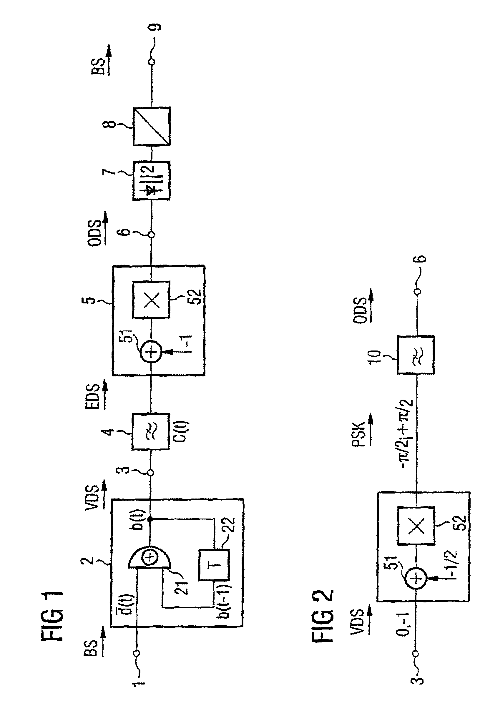
[0015]FIG. 1 shows a known arrangement for duobinary coding of an optical signal. This includes a series circuit formed by a precoder 2, whose data input 1 is supplied with a (possibly inverted) binary signal BS, an electrical filter 4 and a phase modulator 5, at whose output 4 an optical duobinary signal ODS is emitted. A Mach-Zehnder modulator 52 with a drive circuit 51 is used as the modulator 5. Elements which are not significant to the present invention are not illustrated.

[0016]The precoder 2, in this case in the form of an exclusive-OR gate 21 and a delay element 22 (which, if required, also contains an inverter), sconverts the binary signal BS, which has the states 0 and 1, to a precoded duobinary signal VDS in accordance with the function b(t)= d(t)⊕b(t−1). The filter 4 which is used as a coder, uses this to produce a duobinary signal EDS with the states 0, 1 and 2, by superimposition of the binary states. The drive circuit 51 converts these states to suitable drive signals...


PUM


Abstract

A method and system for duobinary coding of optical signals, wherein a precoded duobinary signal is supplied to a phase modulator which converts it to a phase-modulated optical signal, an optical filter carries out the function of the coder and converts the phase-modulated signal to an optical duobinary signal, and the duobinary coding results in a reduction in the bandwidth. A wavelength division multiplex system is provided by precoding a number of binary signals and converting them to phase-modulated signals, which are in turn, combined via an optical multiplexer, wherein the multiplex signal formed in this way is supplied to an optical filter which operates simultaneously as a coder for all the signals and produces a group of duobinary signals, and a number of groups of duobinary signals can be interleaved in one another in order to produce a dense wavelength division multiplex signal.

Description

BACKGROUND OF THE INVENTION[0001]Duobinary coding is advantageously used in transmission systems in order to reduce the transmission bandwidth or to increase the transmission capacity. In the case of duobinary coding, a special case of partial response binary coding, a binary data signal is converted to a three-stage signal using a specific coding rule. The bandwidth requirement for this ternary transmission signal is, in consequence, halved in comparison to that of a binary data signal. The code, which was originally developed for transmission of electrical signals, is also used for the transmission of optical signals, owing to these characteristics.[0002]The use of this code is also explained for optical signal transmission in the journal “Journal of Lightwave Technology”, Vol. 16, No. 5, May 1998, pages 788 to 797, “Characteristics of Optical Duobinary Signals in Terabit / s Capacity, High-Spectral Efficiency WDM Systems”, Takashi Ono et al. The duobinary signals are converted to a...

Claims


Application Information

Patent Timeline
Patent Type & Authority Patents(United States)
IPC IPC(8): H04J14/00H03M7/06
CPCH03M7/06
Inventor ROSENKRANZ, WERNERWREE, CHRISTOPH
Owner XIEON NETWORKS SARL
Why Eureka
Try Eureka