
Radio frequency MEMS switch contact metal selection

a technology of contact metal and switch, which is applied in the direction of contacts, solid-state devices, relays, etc., can solve the problems of low resistance, increased contact resistance, and switch becoming stuck in the closed position, and achieves desirable mechanical wear resistance and easy and fast implementation

Inactive Publication Date: 2007-06-26
AIR FORCE UNITED STATES OF AMERICA THE AS REPRESENTED BY THE SEC OF
View PDF19 Cites 10 Cited by
  • Summary
  • Abstract
  • Description
  • Claims
  • Application Information

AI Technical Summary

Benefits of technology

[0008]It is therefore an object of the present invention to provide an easy and quickly implemented gold inclusive microelectromechanical alloy selection arrangement.
[0009]It is another object of the invention to provide a MEMS contact arrangement affording desirable mechanical wear resistance.
[0014]It is another object of the invention to provide microelectromechanical switch contacts affording desirable low susceptibility to oxidation contaminant gettering and sulfide layer formation.

Problems solved by technology

The two primary failure mechanisms for metal contact switches involve the switch becoming stuck in the closed position (i.e. stiction) or incurring increasing contact resistance as a result of increasing switch operating cycles.
This low resistance results of course from gold's low electrical resistivity and its resistance to surface oxide and sulfide layer formations.
However, MEMS switches with gold electric contacts are prone to the stiction and increased contact resistance failure mechanisms because of gold's relatively low hardness, a hardness of 1-2 GPa is typical.

Method used


Image

  • Radio frequency MEMS switch contact metal selection
  • Radio frequency MEMS switch contact metal selection
  • Radio frequency MEMS switch contact metal selection

Examples


Embodiment Construction

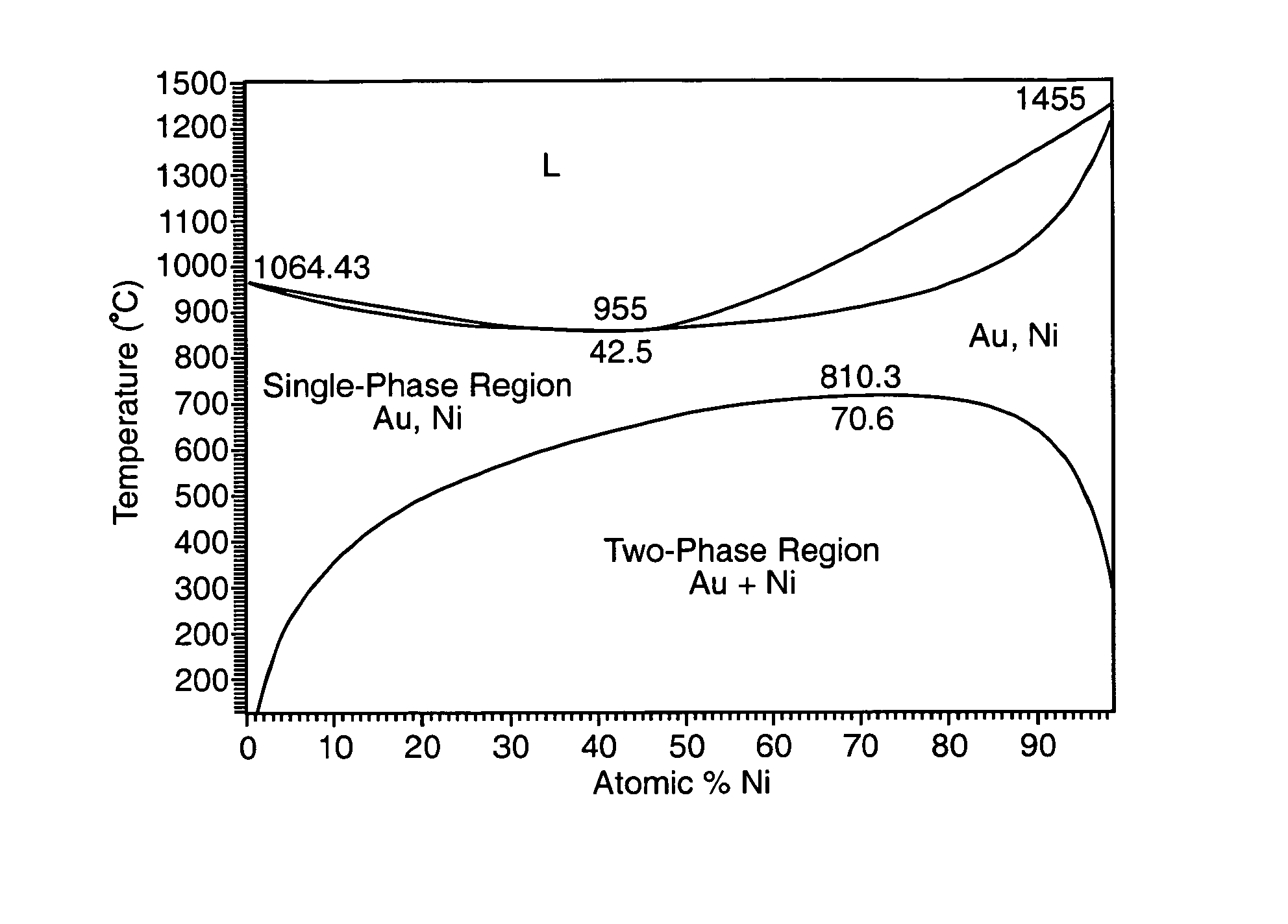
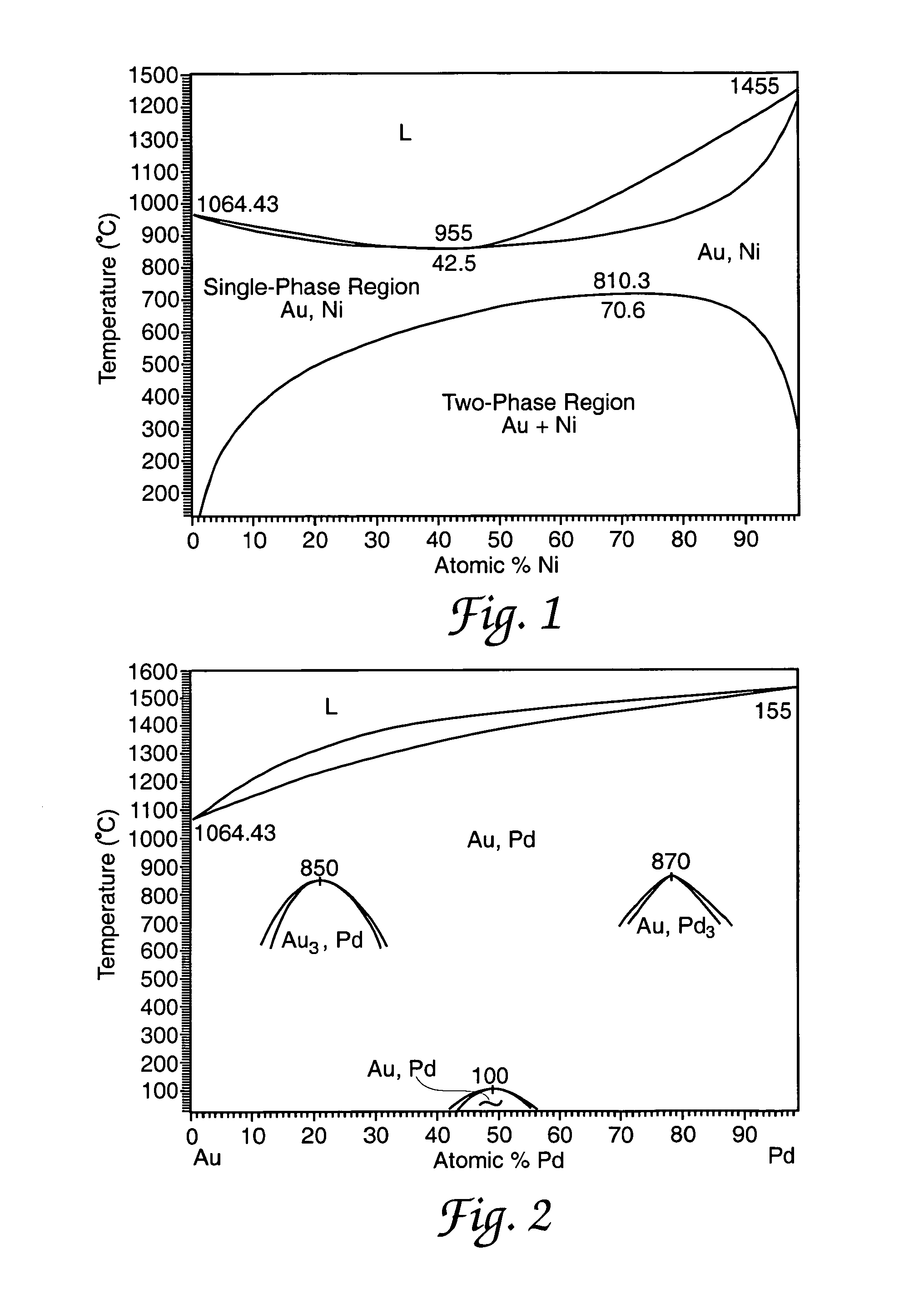
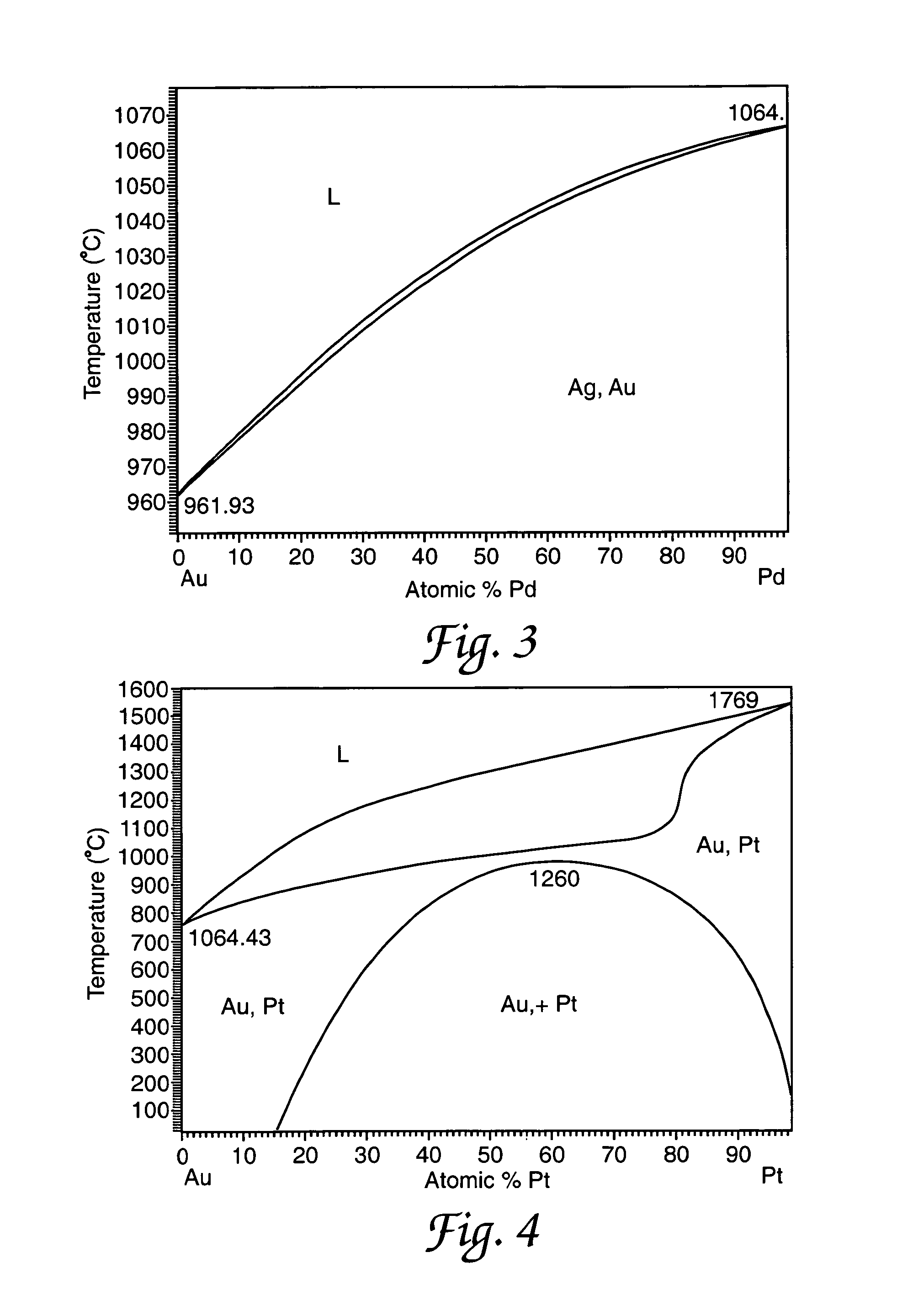
[0036]It is desirable that radio frequency MEMS switch fabrication be consistent and repeatable. Toward this end the present invention includes procedure for selecting alloy electric contact metallurgies for microswitches; measuring Au—Pd, Au—Pt and Au—Ag thin film material properties relating to such contacts; accomplishing fabrication of RF MEMS switches with Au-(6.3 at %)Pt alloy electric contacts, measuring contact resistance and considering switch life cycle test results. The expression (6.3 at %)Pt designates an atomic percentage of Platinum.

[0037]According to the Metals Handbook, “- - - no metal has all the desired properties required to accomplish the objectives of different (switch) contact applications. Intuitively, this generalization appears correct because requirements (i.e. service life, load, etc) change for different switch applications. Desired electric contact properties include low electrical resistance, high thermal conductivity, absence of insulating oxides or s...


PUM

PropertyMeasurementUnit
resistanceaaaaaaaaaa
actuation voltagesaaaaaaaaaa

Abstract

A method for selecting metal alloys as the electric contact materials for microelectromechanical systems (MEMS) metal contact switches. This method includes a review of alloy experience, consideration of equilibrium binary alloy phase diagrams, obtaining thin film material properties and, based on a suitable model, predicting contact electrical resistance performance. After determination of a candidate alloy material, MEMS switches are conceptualized, fabricated and tested to validate the alloy selection methodology. Minimum average contact resistance values of 1.17 and 1.87 ohms are achieved for micro-switches with gold (Au) and gold-platinum (Au-(6.3 at %)Pt) alloy contacts. In addition, ‘hot-switched’ life cycle test results of 1.02×10⁸ and 2.70×10⁸ cycles may be realized for micro-switches with Au and Au-(6.3 at %)Pt contacts. These results indicate increased wear with a small increase in contact resistance for MEMS switches with metal alloy electric contacts.

Description

CROSS REFERENCE TO RELATED PATENT DOCUMENTS[0001]The present document is somewhat related to the copending and commonly assigned patent application document “SHAPED MEMS CONTACT”, Ser. No. 11 / 047,345 filed of even date herewith. The contents of this related even filing date application are hereby incorporated by reference herein.RIGHTS OF THE GOVERNMENT[0002]The invention described herein may be manufactured and used by or for the Government of the United States for all governmental purposes without the payment of any royalty.BACKGROUND OF THE INVENTION[0003]Radio frequency microelectromechanical systems (MEMS) switches are of paramount in importance for future miniaturizations of radio frequency systems. Space-based radar, phased array radar and phase shifters all depend on being able to easily and reliably switch between different radio frequency loads. Because of their small geometries, exceptional performance and low power consumptions, MEMS metal contact switches are well suite...

Claims


Application Information

Patent Timeline
Patent Type & Authority Patents(United States)
IPC IPC(8): H01H57/00
CPCH01H59/0009H01H2001/0052
Inventor COUTU, JR., RONALD A.KLADITIS, PAUL E.CRANE, ROBERT L.LEEDY, KEVIN D.
Owner AIR FORCE UNITED STATES OF AMERICA THE AS REPRESENTED BY THE SEC OF
Learn More