
Geothermal heating and cooling system with solar heating

a geothermal heating and cooling system technology, applied in the field of improvement, can solve the problems of inability to utilize geothermal heat transfer, difficult construction, and inability to meet the needs of geothermal heat transfer, and achieve the effect of increasing the overall system operational efficiency

Inactive Publication Date: 2007-06-26
EARTH TO AIR SYST
View PDF24 Cites 127 Cited by
  • Summary
  • Abstract
  • Description
  • Claims
  • Application Information

AI Technical Summary

Benefits of technology

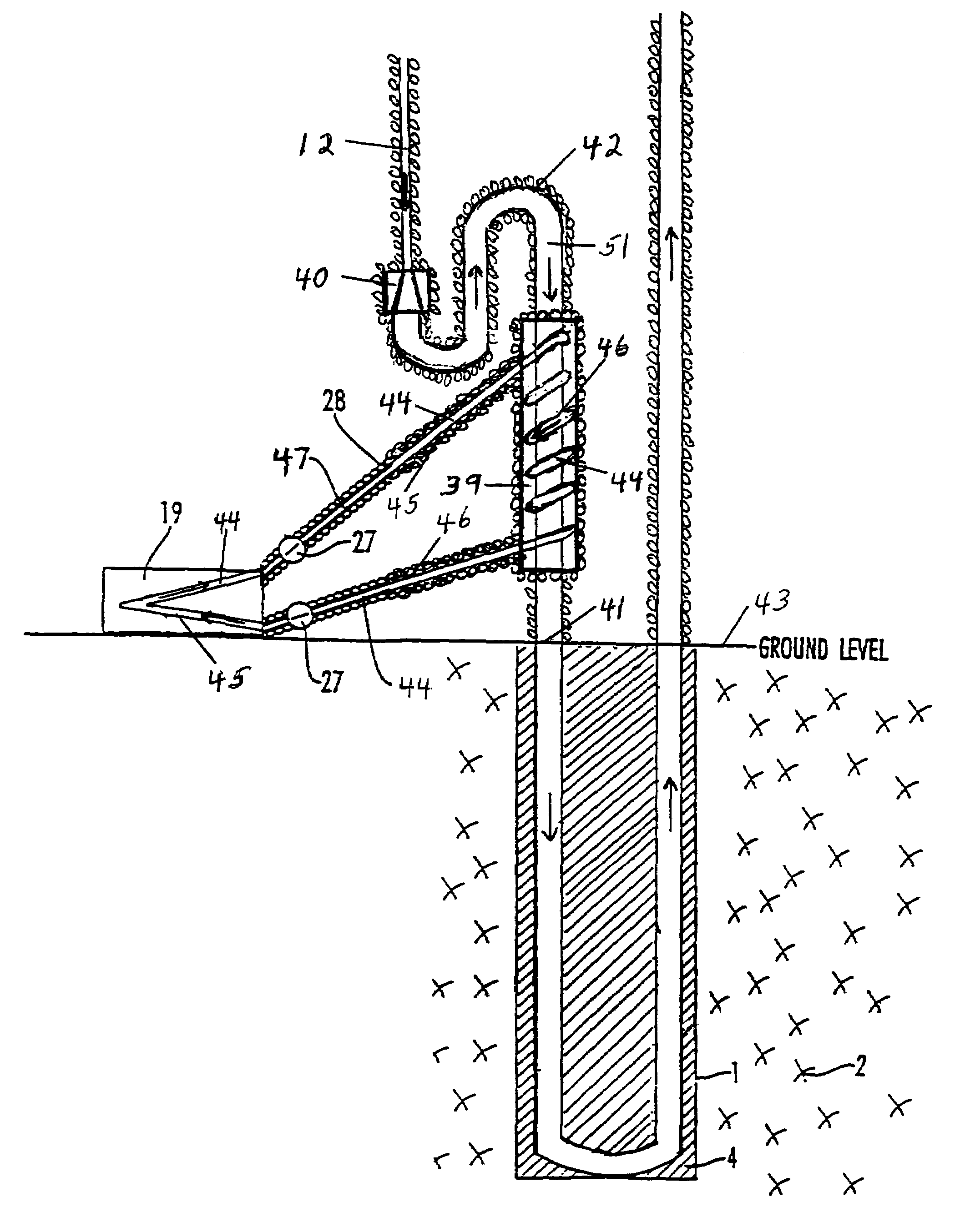
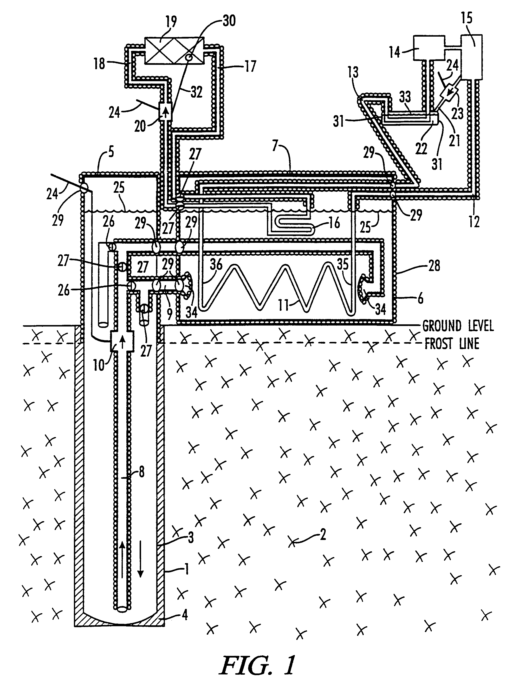
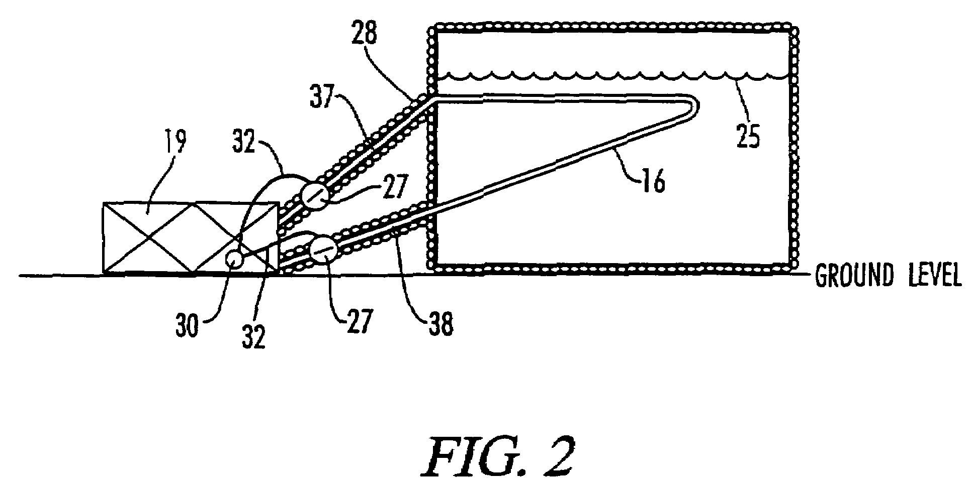
[0015]It is an object of the present invention to further enhance and improve the efficiency and installation cost functionality of predecessor geothermal heat exchange designs for closed-loop water-source heat pump systems, and for direct expansion heat pump systems. This is accomplished by means of a solar heat collector solar system that is operatively connected to a new, or to an existing, geothermal direct expansion, or closed-loop water-source, heat pump system so as to provide supplemental heat in the heating mode, when advantageous, by means of natural solar heat collector fluid convection.
[0016]More specifically, a borehole is drilled to a specified depth, depending on the amount of heat transfer desired, and a casement, such as a six inch diameter steel or plastic casement, which casement has been sealed at the bottom and at all joint areas along the sides, is inserted into the full depth of the borehole. Next, a smaller diameter, such as a two and one-half inch diameter open-ended plastic pipe, which has been fully insulated, is inserted to a depth near, within about six to twelve inches, the bottom of the sealed casement. The sealed primary casement extends to a point near, or above, the surface where the open-ended plastic pipe connects to a sealed container, such as a plastic tub. The plastic tub and the primary casement are fully insulated above-ground and to a depth at least equal to the maximum frost / heat line. Heat exchange coils, such as copper refrigerant tubing, having sufficient surface area to transfer the desired amount of heat, are placed into the sealed container, with an insulated supply and return refrigerant line extending to a conventional heat pump system, comprised of a compressor, an expansion valve, an interior air handler, and other customary equipment well-known to those in the trade. The sealed container, casement, and open-ended pipe are all then filled with a heat transfer liquid, such as water and / or water and anti-freeze, and a liquid circulating pump is attached near the top of the pipe so as to pull liquid up through the open-ended pipe from the bottom of the casement deep underground. As the liquid from the bottom of the casement is pulled up through the insulated pipe, the liquid from the bottom of the casement, which is cool in the summer and warm in the winter, will circulate over the refrigerant heat transfer line, which are hot in the summer and cold in the winter, and the liquid will be pulled back to the bottom of the casement, where heat supplied to, or taken from, the liquid, through the walls of the copper refrigerant heat transfer line by the circulating refrigerant, will be transferred to the surrounding geothermal soil and / or rock and / or water by means of natural heat convection as the liquid travels to the bottom of the casement. Since the central pipe diameter is relatively large, and since the diameter of the casement is larger than the pipe, frictional efficiency losses will be minimized and efficiencies significantly increased. Further, since the pipe inside the casement is fully insulated, the common “short circuiting” heat transfer effect between the supply and return liquid lines will be substantially eliminated.
[0017]The subject invention also discloses a means of providing the warmest water from the bottom of the casement to the exiting portion of the refrigerant traveling to the compressor in the winter, as well as a means of providing the coolest water from the bottom of the casement to the exiting portion of the refrigerant traveling to the interior air handler in the summer, by means of an arrangement of piping and solenoid and / or check valves designed to switch liquid flow direction into and out of the container in a fashion commensurate with the desired refrigerant flow direction in either of the heat pump system's operational heating or cooling modes. Also, a diffuser is incorporated at the entering / exiting portion of the liquid supply / return tubes within the container so as to provide relatively even heat distribution along the refrigerant heat exchange line(s) within the container. This will enhance system efficiencies, as well as help to ensure that the warmest sensible air is provided to the interior conditioned air space in the winter, and that the coolest sensible air is provided in the summer.

Problems solved by technology

While open-loop systems can significantly reduce plastic tubing excavation or drilling requirements on a system capacity tonnage basis, if an adequate water supply is available, these systems pose a potential environmental threat since bacteria in the surface water transport tubing can be transferred to, and can infect, the water which is being rejected back into the public water supply.
Historically, due to compressor operational limitations encountered with traditional DX designs installed at depths beyond 50 to 100 feet, most reverse-cycle DX systems, which operate in both the heating and the cooling modes, have been installed with an array of horizontal heat exchange tubes about 5 feet deep, or in vertical boreholes less than 100 feet deep.
While this multiple concentric tube design reduces the “short-circuiting” effect, it is practically difficult to build and could be functionally cost-prohibitive.
The problem encountered with insulating the heat transfer return line, by means of fully surrounding a portion of same with insulation as per Kuriowa, or by means of a fully insulated concentric tube within a tube as per Dressler, or by means of a fully insulated return line as per Wiggs' predecessor designs, is that the fully insulated portion of the return line is not exposed to naturally occurring geothermal temperatures, and is therefore a costly necessary underground / underwater system component which is not capable of being utilized for geothermal heat transfer purposes.
Further, of course, even in horizontal and vertical closed-loop water-source heat pump systems, this “short-circuiting” effect, caused by the supply and return water transfer lines being in close proximity to one another, is a problem which deters from operational system efficiencies.
An additional problem encountered with traditional closed-loop water-source systems is the fact that, traditionally, ¾ inch to 2 inch diameter plastic water transfer tubing is utilized, so as to reduce plastic pipe costs and excavation / drilling expenses.
However, as a general principle, smaller pipe sizes have greater friction efficiency losses, which result in increased requisite pumping energy.
However, after a more detailed review and confidential discussion with others, it was determined that the cost, as well as the requisite surface land area requirements, involved were not likely to be advantageous over a conventional direct expansion exterior heat exchange tube installation design, so the proposition was abandoned by Wiggs.
Further, such an installation would still be affected by near-surface temperature fluctuations in both the summer and the winter, and would still be subjected to “short circuiting” efficiency disadvantages encountered by a mixture of heated and cooled container liquid.
Finally, while discussions have been entertained regarding the desirability of incorporating solar heating benefits into a geothermal heat pump heating system, as well as incorporating evaporative cooling benefits into a geothermal cooling system, there have been practical obstacles, such as potential extreme system operational pressure differentials, flash gas problems, system short-cycling, and energy storage issues.

Method used


Image

  • Geothermal heating and cooling system with solar heating
  • Geothermal heating and cooling system with solar heating
  • Geothermal heating and cooling system with solar heating

Examples


Embodiment Construction

[0063]The following detailed description is of the best presently contemplated mode of carrying out the invention. The description is not intended in a limiting sense, and is made solely for the purpose of illustrating the general principles of the invention. It is to be understood that the disclosed embodiments are merely exemplary of the invention, which may be embodied in various forms. Therefore, specific structural and functional details disclosed herein are not to be interpreted as limiting, but merely as a basis for the claims and as a representative basis for teaching one skilled in the art to variously employ the present invention in virtually any appropriately detailed structure or system. The various features and advantages of the present invention may be more readily understood with reference to the following detailed description taken in conjunction with the accompanying drawings.

[0064]Referring now to the drawings in detail, where like numerals refer to like parts or e...


PUM


Abstract

A sealed well direct expansion geothermal heat exchange unit, whose sealed well can be placed in ground and / or in water, consisting of a conventional direct expansion, or other heat pump, system wherein the exterior refrigerant heat exchange lines are placed within an insulated and sealed container, which container is supplied with a circulating heat conductive liquid from and to a sub-surface sealed well encasement, which container liquid may be supplemented with heat from a solar heating system, and which unit's hot refrigerant vapor line may be supplementary cooled by means of condensate water evaporative cooling, as well as a means to provide any direct expansion, and any closed-loop water-source, geothermal heat pump system with an optional solar heating supplement in the heating mode, and with an optional water-cooled vapor line supplement in the cooling mode.

Description

APPLICATION FOR UNITED STATES LETTERS PATENT[0001]This application is a Continuation-In-Part application which claims benefit of co-pending U.S. Patent Application Ser. No. 60 / 439,831 filed Jan. 14, 2003, entitled “Deep Well Direct Expansion Heating / Cooling System”; U.S. Provisional Patent Application Ser. No. 60 / 456,335 filed Mar. 20, 2003, entitled “Deep Well / Long Trench Expansion Heating / Cooling System”; U.S. Provisional Patent Application Ser. No. 60 / 471,585 filed May 19, 2003, entitled “Deep Well / Long Trench Direct Expansion Heating / Cooling System and Retrofit Design”; and U.S. Provisional patent application Ser. No. 10 / 211,112 filed Aug. 2, 2002, entitled “Sealed Well Direct Expansion Heating and Cooling System”, all of which are hereby incorporated by reference. A portion of the disclosure of this patent document contains material that is subject to copyright protection. The copyright owner has no objection to the facsimile reproduction by anyone of the patent document or the...

Claims


Application Information

Patent Timeline
IPC IPC(8): F25B27/00
CPCF24J2/04F24J3/083F24J3/086F25B27/005F25B30/06Y02E10/125Y02E10/16Y02E10/44F24S10/00F24T10/15F24T10/30Y02E10/10
Inventor WIGGS, B. RYLAND
Owner EARTH TO AIR SYST
Learn More