
Pattern generating systems

Inactive Publication Date: 2007-06-05
BI BAOKANG
View PDF22 Cites 53 Cited by
  • Summary
  • Abstract
  • Description
  • Claims
  • Application Information

AI Technical Summary

Benefits of technology

[0015]Accordingly, it is the object of the present invention to provide advanced pattern generating systems that have a greatly simplified system design resulting in reduced system size, improved system performance and reliability.
[0016]It is another object of the present invention to provide pattern generating systems that can generate large-field high-resolution patterns with increased speed and throughput for patterning 2-D or 3-D objects.
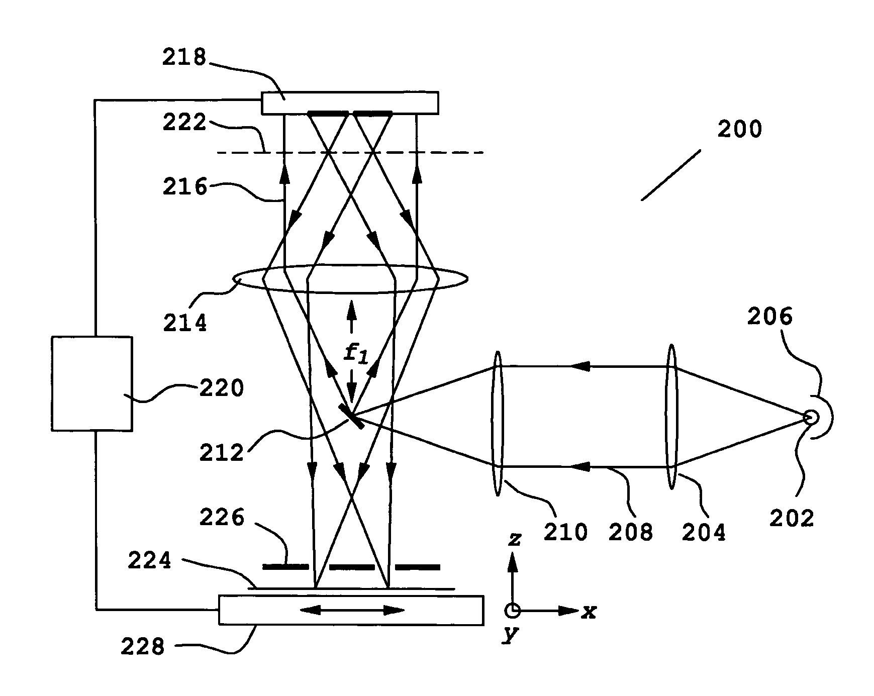
[0021]When used as spot generators, ZPM arrays provide the functions of both a modulator and a focusing lens, eliminating several large components as would be required in conventional art. The integrated approach taken by the ZPM offers substantial improvements in reducing system complexity, improving reliability and stability, in addition to the intrinsic advantages of compactness, high operating speed, and high bandwidth. Accordingly, pattern generating systems incorporating ZPM arrays provide many improvements over prior art such as simplified system design, reduced system size, less maintenance, improved reliability and stability, and increased throughput.

Problems solved by technology

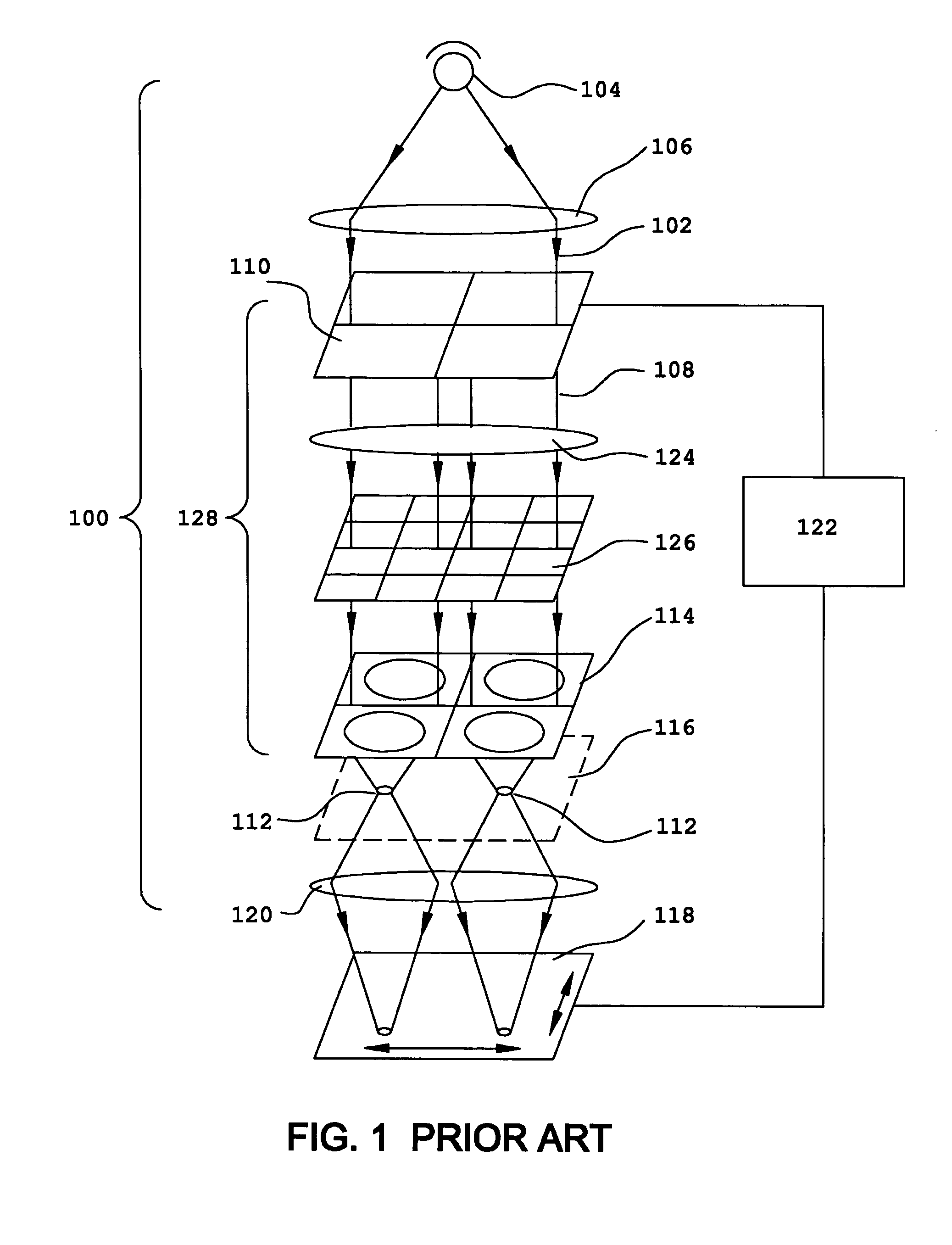
Due to the discrete nature of the critical components used in the conventional art, these high-resolution pattern generating systems all suffer from the problems of being bulky, being susceptible to environmental influences such as temperature change and mechanical vibrations, and having higher system costs.
There are many other problems that relate to the specific system designs.
Larger arrays of microlenses including, for example, one million of lenslets, and having uniform lens properties are very difficult and expensive to fabricate, and are not suited for large-scale manufacturing.
However, the operating speed of this type of high-resolution pattern generating system is limited by the SLM.
The performance was limited by the relative slow response time of the DLP.
However, this type of spot array generators is not suited for directly generating two-dimensional (2-D) images due to the fact that the GLV is essentially an one-dimensional (1-D) linear SLM and can not be configured into a high-density 2-D array.
This type of system is extremely complex and bulky when the number of lens elements becomes large.

Method used


Image

  • Pattern generating systems
  • Pattern generating systems
  • Pattern generating systems

Examples


Embodiment Construction

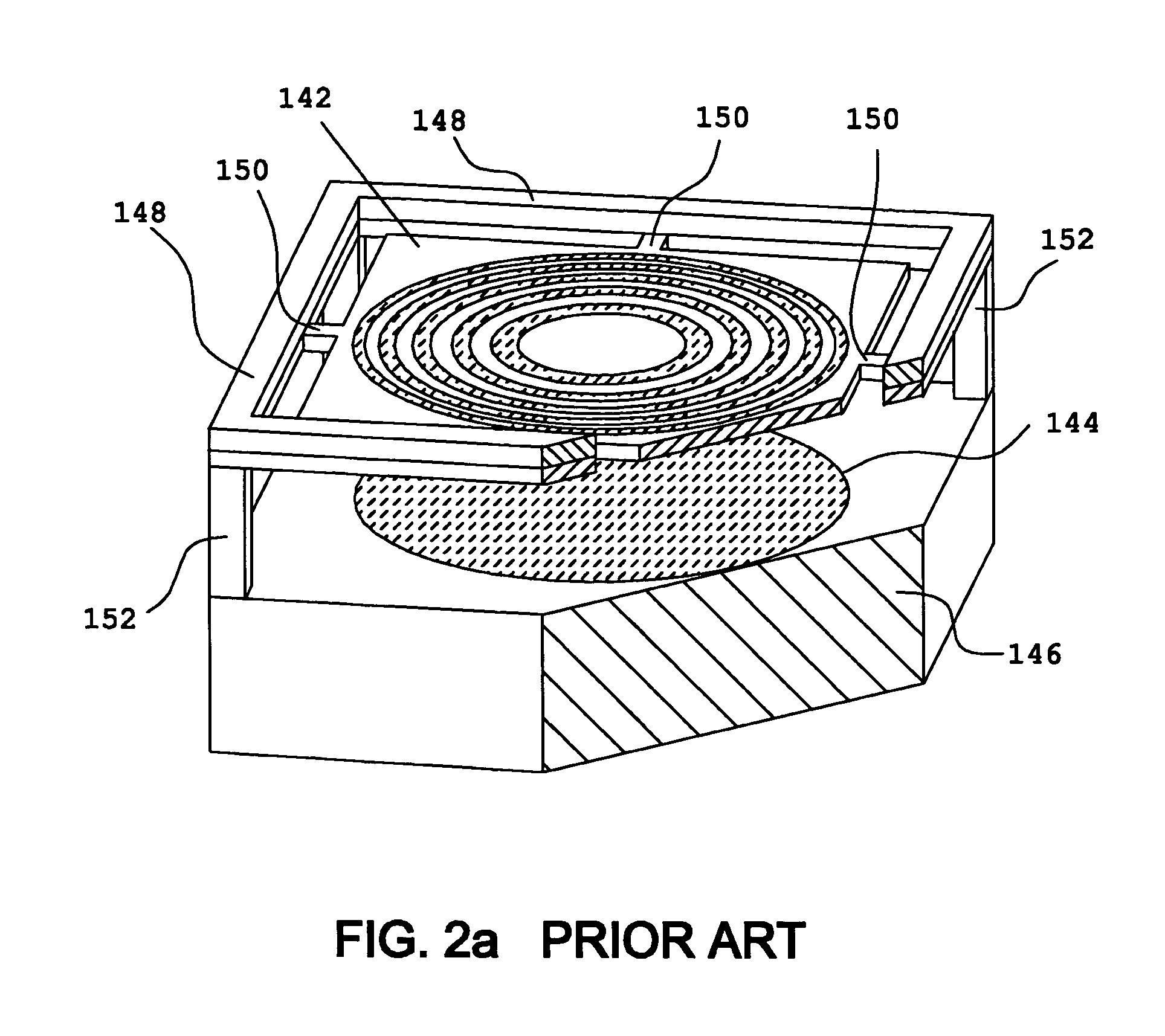
[0059]The pattern generating systems disclosed here in accordance with the present invention include a particularly preferred wave modulating device—a Zone Plate Modulator or a Zone Plate Modulator array. The terminology. “Zone Plate Modulator” or ZPM for short, adopted in this disclosure, refers to a wave modulating device comprising a pair of complementary zone plates and a modulation means for modulating the optical path difference between the two zone plates. Accordingly, the terminology “Zone Plate Modulator array” or ZPM array refers to a device comprising a plurality of ZPM elements and preferably having the ZPM elements arranged into a regular pattern such as a 1-D array or a 2-D array with individual ZPM placed on a square grid. Each ZPM element in a ZPM array operates independently according to the control signal.

[0060]The principles of ZPMs are described in detail in U.S. patent application Ser. No. 10 / 707,257, filed by the same applicant of the present invention, the dis...


PUM


Abstract

A pattern generating system for generating two-dimensional images on a surface includes a light source and one or more Zone Plate Modulator (ZPM) arrays. The ZPM arrays comprise diffractive zone plate modulating elements that are capable of either diffracting or reflecting an incident light according to the image data. In a high-resolution pattern generating system, ZPM arrays are used as spot array generators. A complete high-resolution image is formed by scanning individual light spots in the spot array using a subfield scanning means.

Description

BACKGROUND OF INVENTION[0001](1) Field of the Invention[0002]The present invention relates to systems for generating high-resolution optical patterns. In particular, the present invention relates to systems that incorporate Zone Plate Modulators or array of Zone Plate Modulators for generating high-resolution patterns.[0003](2) Brief Description of Prior Art[0004]Optical pattern or image generating systems are widely used in many industries. For example, in the semiconductor industry high-resolution lithographic systems are used for fabricating photomasks and for direct exposing photoresist coated wafers (maskless lithography). In commercial printing press, high-resolution printing systems are used for generating offset plates. In the rapid prototyping industry, high-resolution stereo lithography or three-dimensional (3-D) lithography is employed for making various 3-D objects. High-resolution, large area projection displays are also becoming the choice for technical presentations a...

Claims


Application Information

Patent Timeline
IPC IPC(8): G03B27/54
CPCG03F7/70275G03F7/70291B33Y30/00B33Y80/00
Inventor BI, BAOKANG
Owner BI BAOKANG
Learn More