
Liquid crystal television receiver

a television receiver and liquid crystal technology, applied in the field of liquid crystal television receivers, can solve the problems of increasing the cost of components, increasing the number of components, and the instability of the electric power supply, and achieve the effect of reducing the cos

Inactive Publication Date: 2007-06-05
FUNAI ELECTRIC CO LTD
View PDF14 Cites 3 Cited by
  • Summary
  • Abstract
  • Description
  • Claims
  • Application Information

AI Technical Summary

Benefits of technology

This configuration reduces the number of components, prevents noise interference, and stabilizes voltage, ensuring efficient operation of the liquid crystal television receiver without the need for a charge pump, thus lowering costs and maintaining receiver sensitivity.

Problems solved by technology

However, an electric power supply has a slight instability in some regions, where a stabilizing mechanism is necessary for a television receiver.
The use of the first related art causes the following problems.
This has resulted in increase in the number of components and in rise in the cost of the components.
Thus, from the viewpoint of resolving the problems of the first related art, the second related art is difficult to apply.

Method used


Image

  • Liquid crystal television receiver
  • Liquid crystal television receiver
  • Liquid crystal television receiver

Examples


Embodiment Construction

[0021]Hereinafter, an embodiment of the invention is described by referring to the accompanying drawings.

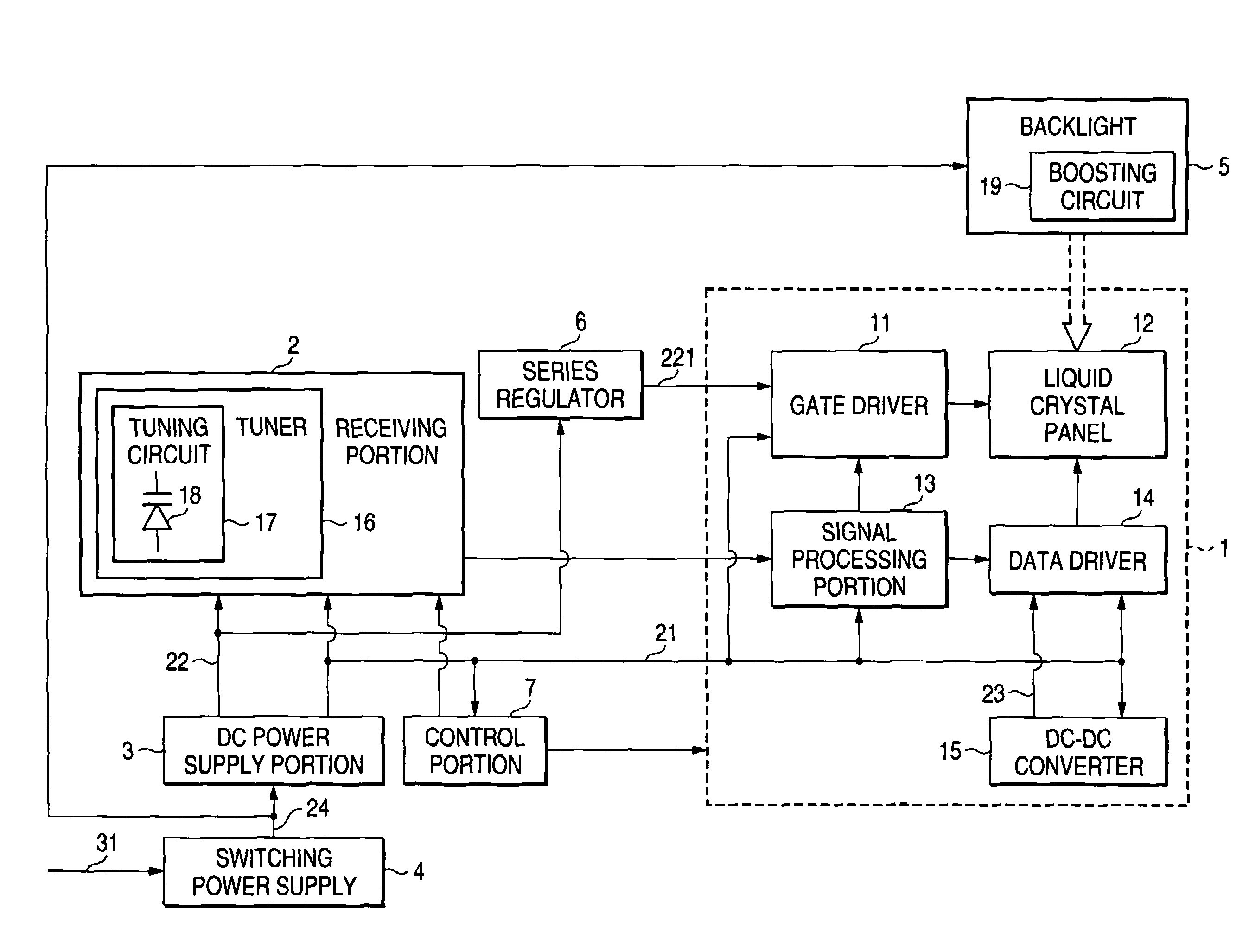
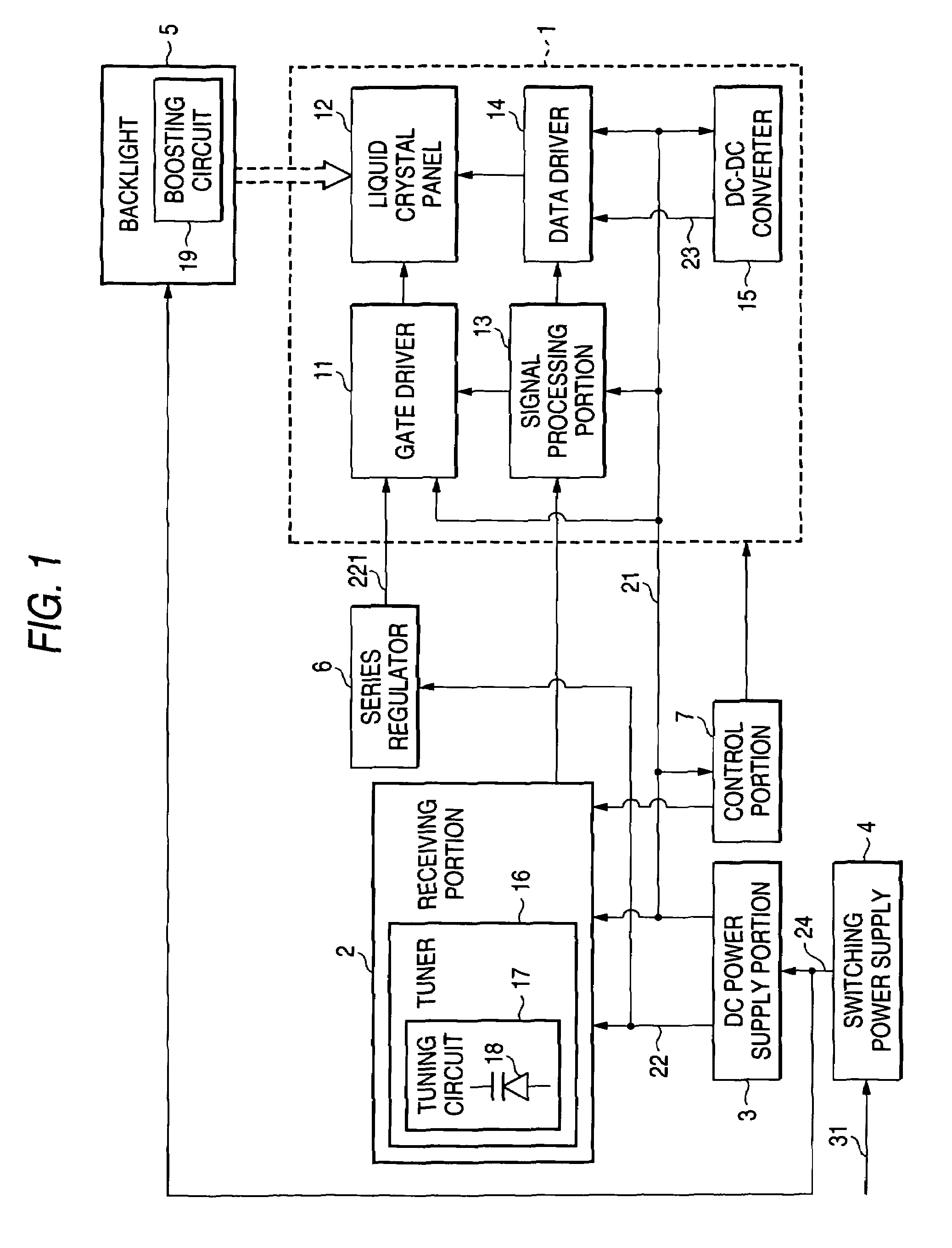
[0022]FIG. 1 is block diagram showing the electrical configuration of an embodiment of a liquid crystal television receiver according to the invention. In this figure, a block, whose configuration is the same as that of a component of the related art shown in FIG. 3, is designated by reference character, which is the same as that denoting the component of the related art in FIG. 3.

[0023]As illustrated in FIG. 1, a switching power supply 4 generates 12 V DC power from a commercial power source 31. Then, the switching power supply 4 sends the generated 12 V DC power 24 to the DC power supply 3 and the backlight 5. The DC power supply 3 generates 3.3 V DC power 21 from the 12 V DC power 24. Also, the DC power supply 3 generates 33 V DC power 22 serving as analog power (tuning DC power) used for permitting a tuner 16 of the receiving portion 2 to use the tuning frequency of a tuning ...


PUM

PropertyMeasurementUnit
voltagesaaaaaaaaaa
voltageaaaaaaaaaa
voltageaaaaaaaaaa

Abstract

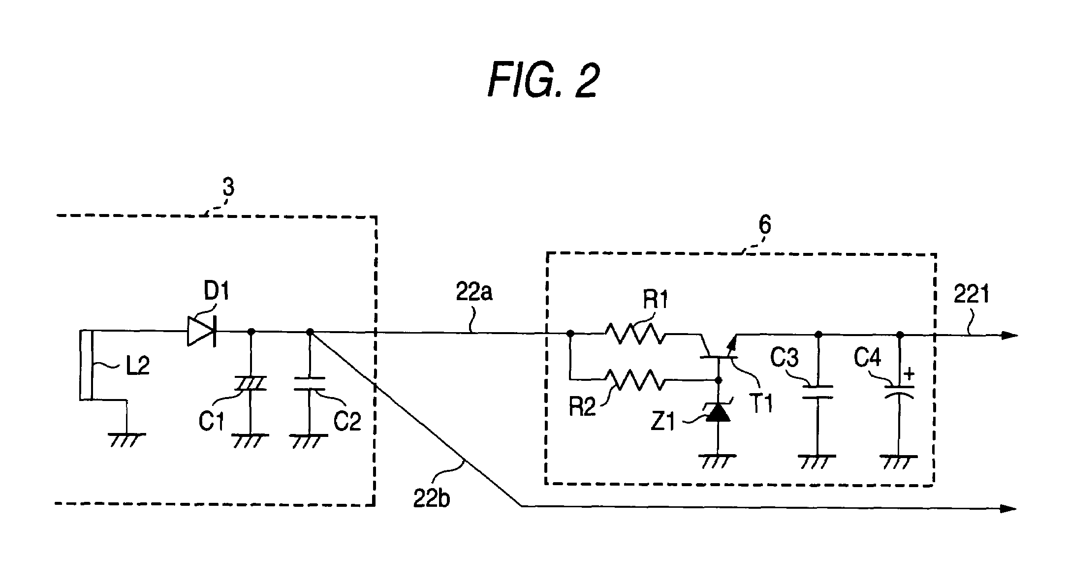
A liquid crystal television receiver includes a DC power supply to generate and output tuning DC power, a receiving portion, a display portion, and a series regulator. Preferably, the receiving portion is fed the tuning DC power and receives a video signal, the display portion includes an active-matrix liquid crystal panel, a gate driver to generate a gate-on signal and drive a gate line and a data driver to drive a data line, allowable ranges of voltage of the tuning DC power and the gate-on DC power share a common range in which a voltage of the tuning DC power is set, the tuning DC power is fed to the gate driver, and the series regulator is provided on at least one of power supply paths to feed the tuning DC power from the DC power supply to the gate driver and to the receiving portion, and removes noise component.

Description

BACKGROUND OF THE INVENTION[0001]1. Field of the Invention[0002]The present invention relates to a liquid crystal television receiver having a receiving portion, which uses a variable-capacitance diode as an element of a receiving tuning circuit, and a display portion using a liquid crystal panel as a display device.[0003]2. Description of the Related Art[0004]As shown in FIG. 3, in a television receiver (hereunder referred to as first related art) employing a liquid crystal panel as a display device, a display portion 91 for displaying video signals outputted from a receiving portion 2 is provided with a gate driver 11 for driving gate lines of the liquid crystal panel 12, and with a data driver 14 for driving data lines thereof. Further, the display portion 91 is also provided with a DC power supply portion 3 for generating and outputting 3.3 V DC power 21 needed by the receiving portion 2. Moreover, the DC power supply portion 3 generates and outputs 3.3 V tuning DC power 22 requ...

Claims


Application Information

Patent Timeline
Patent Type & Authority Patents(United States)
IPC IPC(8): H04N3/14H04N5/63G02F1/133G09G3/20G09G3/36
CPCG09G3/3696H04N5/63G09G3/3677
Inventor KITA, TATSUYA
Owner FUNAI ELECTRIC CO LTD
Learn More