Particle deposition apparatus and methods for forming nanostructures

a nanostructure and particle deposition technology, applied in the field of small-scale structure formation, can solve the problem of difficulty in forming the individual geometric features of these devices at a sufficient degree of resolution, and achieve the effect of small-scale geometric features

Inactive Publication Date: 2007-05-29
QUNANO
View PDF20 Cites 48 Cited by
  • Summary
  • Abstract
  • Description
  • Claims
  • Application Information

AI Technical Summary

Benefits of technology

[0009]It is an object of the present invention to provide an improved method by which devices having very small geometric features may be fabricated.
[0016]A significant advantage of employing a stamp is that a complex configuration of electrically charged regions of predetermined shape, extending over a wide area, may be formed in a single operation. The process of the invention is therefore very much faster to carry out than other methods, such as electron beam drawing or writing.

Problems solved by technology

As sizes are reduced, it becomes difficult to form the individual geometric features of these devices at a sufficient degree of resolution due to the need to employ radiation of ever-shorter wavelengths to expose the photoresist.

Method used


Image

  • Particle deposition apparatus and methods for forming nanostructures
  • Particle deposition apparatus and methods for forming nanostructures
  • Particle deposition apparatus and methods for forming nanostructures

Examples


Embodiment Construction

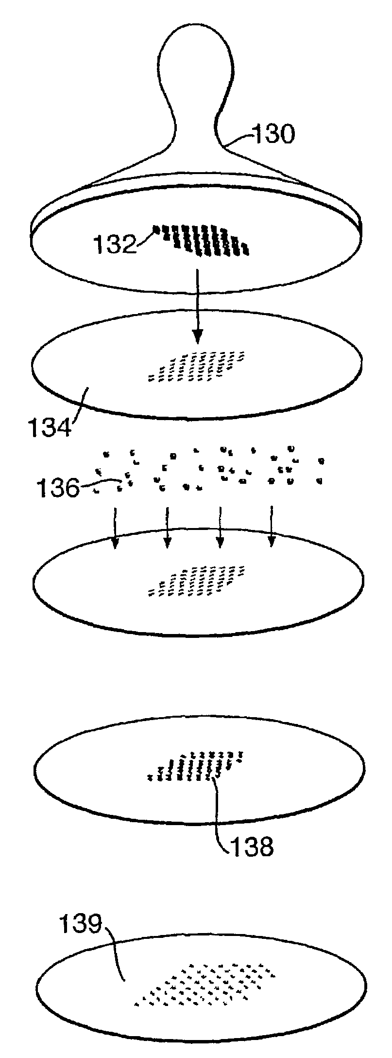
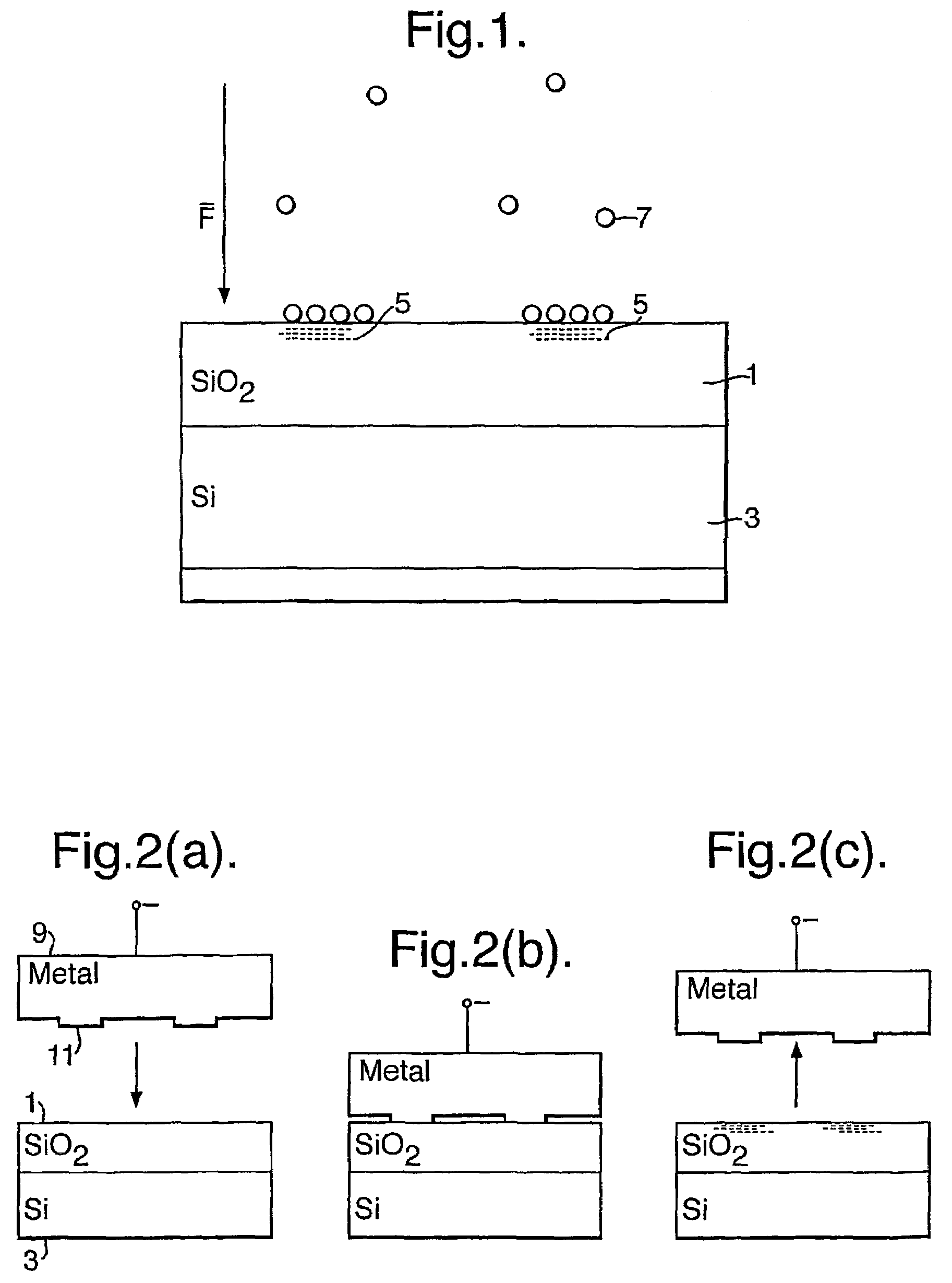
[0031]Referring now to the FIG. 1 of the drawings, the surface of a silicon wafer 3 is oxidised to produce a silicon dioxide layer 1, and localised regions 5 of negative charge are imprinted on the surface. Nanoparticles 7 formed in an aerosol unit are impressed with a positive charge and are attracted to the locally charged regions 5 of the silica surface layer, with the assistance of a local electric field F.

[0032]One method of applying the local charge to the surface is illustrated in FIG. 2a to 2c. A nanoprinting stamp 9 is made from a conducting material (or from an insulator coated with a metal), and is brought into contact with the insulating surface 1. The stamp 9 has protrusions 11 formed on its contact surface in a predetermined configuration. The width of these protrusions may range from dimensions of nanometers up to the macroscopic millimeter range, preferably fabricated by electron beam lithography. The height of the protrusions is not material to the region definition...


PUM

PropertyMeasurementUnit
sizeaaaaaaaaaa
diameteraaaaaaaaaa
diameteraaaaaaaaaa

Abstract

A fast method of creating nanostructures comprising the steps of forming one or more electrically-charged regions (5) of predetermined shape on a surface (1) of a first material, by contacting the regions with a stamp for transferring electric charge, and providing electrically charged nanoparticles (7) of a second material, and permitting the particles to flow in the vicinity of the regions, to be deposited on the regions.

Description

[0001]This invention relates to a method of forming structures of small dimensions, for example of nanometer dimensions—commonly known as nanostructures—and also relates to methods involving interaction of small particles, especially nanometer dimensioned particles with material surfaces.[0002]Hitherto, small-scale photonic or electronic devices have been fabricated using photolithographic processing techniques. As sizes are reduced, it becomes difficult to form the individual geometric features of these devices at a sufficient degree of resolution due to the need to employ radiation of ever-shorter wavelengths to expose the photoresist.[0003]A process that presses a mould into a thin thermoplastic polymer film on a substrate to create vias and trenches with a minimum size of 25 nm is disclosed in “Imprint of sub-25 nm vias and trenches in polymers” Chu et al, Applied Physics Letters 67(21), 20 Nov. 1995, pages 3114–3116.[0004]Nanometer-sized metal and semiconductor particles (nanop...

Claims


Application Information

Patent Timeline
Patent Type & Authority Patents(United States)
IPC IPC(8): B05D1/04B82B3/00B05D1/00G03F7/00H01L21/28H01L49/00
CPCB05D1/007B82Y10/00H01L49/006G03F7/0002H01L21/28273B82Y40/00H01L29/40114H10N99/05G03F7/00B82B1/00B82B3/00
Inventor DEPPERT, KNUT WILFRIEDMAGNUSSON, CARL MARTIN HALLSAMUELSON, LARS IVARKRINKE, THOMAS JOHANNES
Owner QUNANO
Why Eureka
Try Eureka