
Turbine wheel for driving rapidly rotating tools

a technology of rotating tools and turbine wheels, which is applied in the direction of wind motor combinations, rotocraft, wind energy generation, etc., can solve the problems of limited quantity of paint or lacquer to be applied to the dome in any time unit, and achieve the effects of less radius of curvature, greater curvature, and efficient production

Inactive Publication Date: 2007-05-29
GAT GES FUR ANTRIEBSTECHN
View PDF25 Cites 11 Cited by
  • Summary
  • Abstract
  • Description
  • Claims
  • Application Information

AI Technical Summary

Benefits of technology

[0008]One purpose of the invention is to provide a turbine, or turbine wheel, which fits into conventional turbine housings with, at most, slight modification, and which has an even higher torque than previous turbine wheels at the required high rotational speeds. A greater quantity of lacquer can be applied to the spraying dome or a spraying disk without a detrimental braking effect, so that surfaces to be painted can be provided with a uniform coat of paint in an even shorter time than was previously possible.
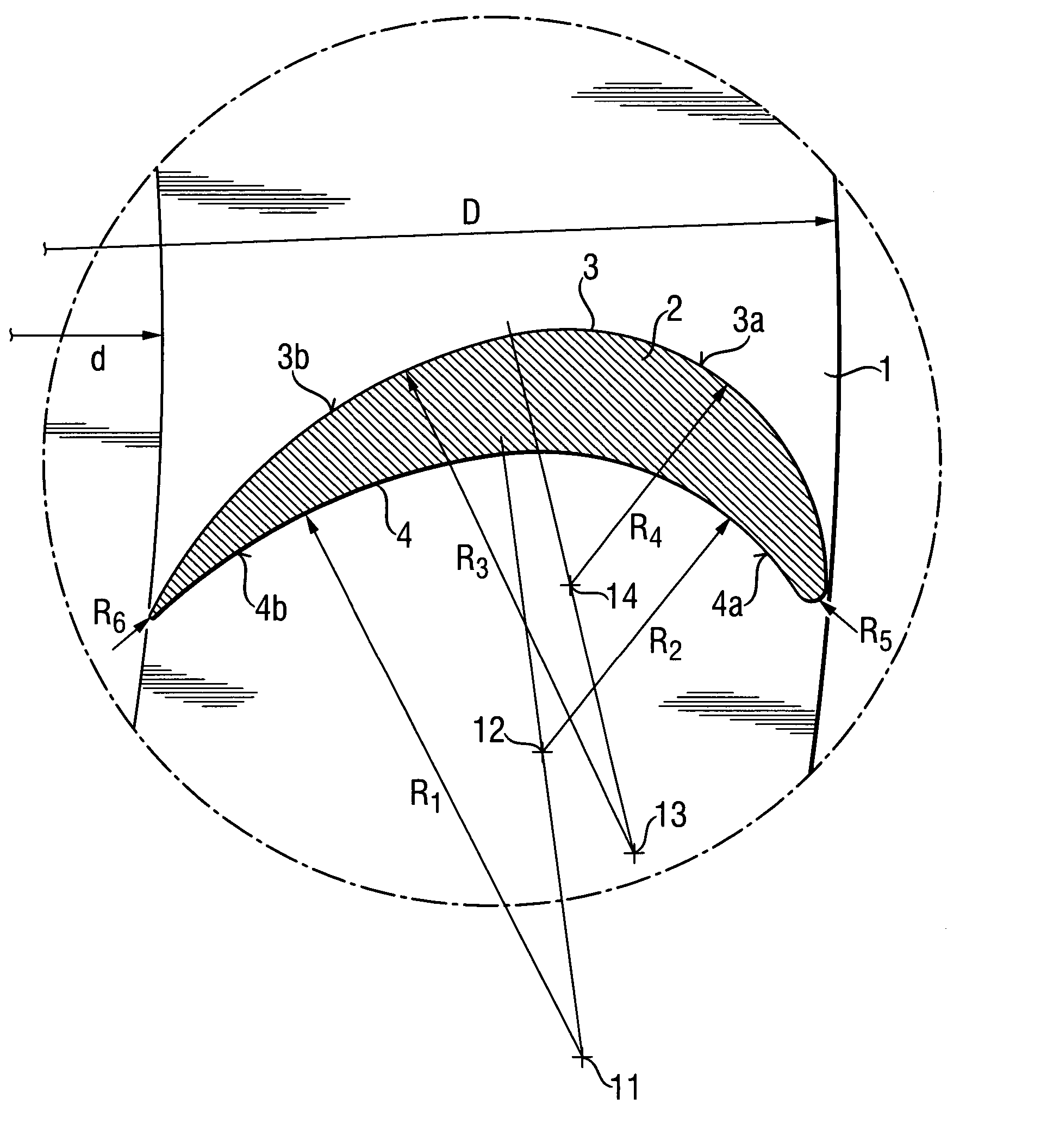
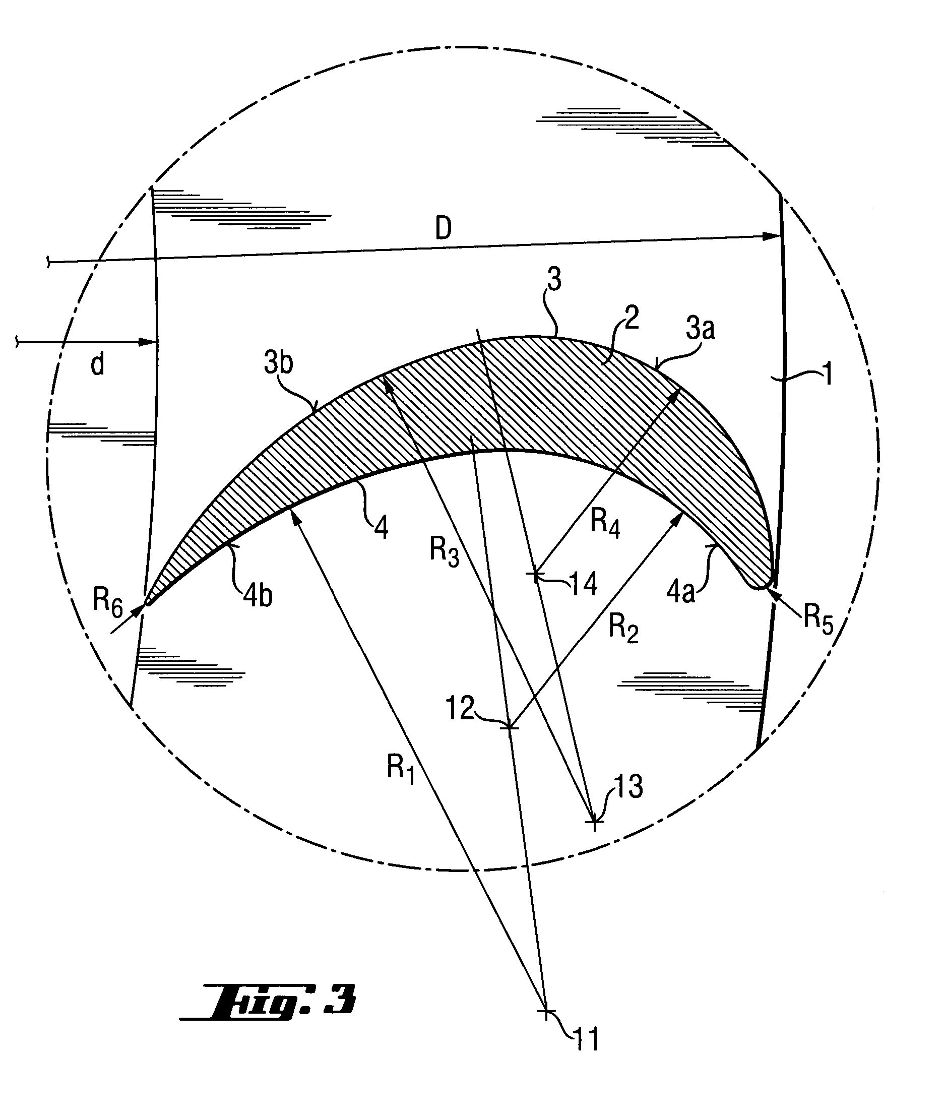
[0010]The individual turbine blades have a constant profile over their axial length, making possible the production of respective profiles in long lengths corresponding to a multiple of the axial length of an individual turbine blade. The individual turbine blades are produced by cutting off or paring off a corresponding portion from this profile. This makes exceptionally efficient production possible. It is also not a significant problem if the radially outer portions of the turbine blades, that is, in the finished turbine wheel, the portions distant from the center of the turbine wheel, have a lesser radius of curvature, and consequently a greater curvature than the radially inward portions of the turbine blades. This is the case on both the front side and the back side of the turbine blades.
[0011]It has been found that such a profile of the turbine blades generates fewer interfering eddies, and results in a more circular and more even running of a turbine wheel with a stable torque. At the same time, the turbine blade design also enables the axial length of the blades to be increased. In conventional turbine blades used for air-suspended turbines with high rotational speeds (70,000 rpm), the axial length of the turbine blade is only approximately 50% of the radial extent of the turbine blades, that is, the difference between the external radius and the internal radius of the blade ring.
[0012]By contrast, in the present invention the axial length of a turbine blade is at least 60%, and preferably more than 65%, of the radial extent of the respective turbine blade. An axial blade length which is approximately 70% of the radial extent of the blade has been found to be expedient and easily controllable. If possible, a value of no more than approximately 80%, but at most, approximately 100%, should not be exceeded for the axial length of the blades relative to their radial extent.

Problems solved by technology

Therefore, in order that the rotational speed of the turbine is not excessively reduced, which would have a detrimental effect on the evenness and fineness of the droplet formation, the quantity of paint or lacquer to be applied to the dome in any unit of time is limited.

Method used


Image

  • Turbine wheel for driving rapidly rotating tools
  • Turbine wheel for driving rapidly rotating tools
  • Turbine wheel for driving rapidly rotating tools

Examples


Embodiment Construction

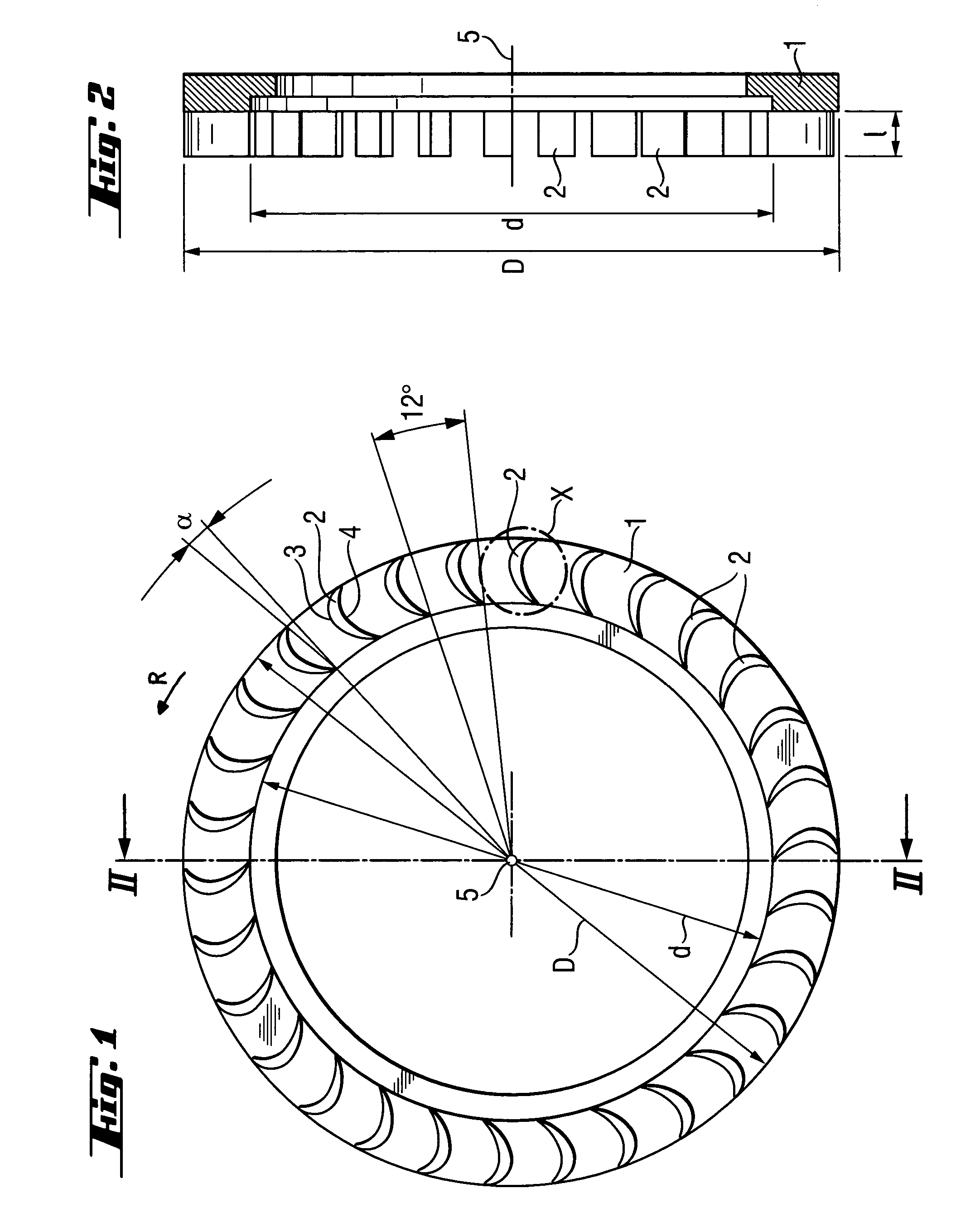
[0027]FIG. 1 shows a turbine wheel with carrier plate 1, in the form of a circular disk, which has an external diameter “D.” On the outer margin of carrier plate 1 is a ring of turbine blades 2, the outer edges of the turbine blades being located approximately on the outer circumference, whereas the inner edges of the blade wheel ring define an inner diameter “d,” as also indicated in FIG. 2. Specifically, the values for “d” are between about 40 and 48 mm, preferably aboout 44 mm, and the values for “D” are between about 50 and 60 mm, preferably 55 mm, the difference “D−d” being approximately 20% of “D.” The corresponding radii, of course, are half the respective diameter values.

[0028]As also shown in FIG. 1, the individual blades are tilted forward by an angle “α” relative to the radial direction, such that the outer edge of a turbine blade is somewhat ahead of the inner edge in the direction of rotation “R.” Specifically, the angle “α,” which is the angle of a connecting line of t...


PUM


Abstract

A turbine wheel for driving rapidly rotating tools, in the form of a circular disk or ring, configured for mounting so as to be rotatable about an axis. Disposed thereon in circular formation are turbine blades having axially parallel front and back faces curved in the radial direction. The front face has a lesser radius of curvature (R3, R4), at least in portions, than the back face. This feature allows the turbine wheel to fit into the conventional turbine housings without relatively major redesign and with, at most, slight modifications. The turbine wheel can achieve higher torque than previous turbine wheels at the required high rotational speeds. Thus, a greater quantity of material can be applied to the spraying dome or a spraying disk without a detrimental braking. Surfaces to be sprayed can be provided with a uniform coat of material in shorter time.

Description

BACKROUND OF THE INVENTION[0001]1. Field of the Invention[0002]The present invention relates to rotating tools, more particularly to turbine wheels for driving rapidly rotating tools.[0003]2. Discussion of Related Art[0004]Turbine wheels for painting equipment are already in use. In these, the paint-spraying domes emit a colored lacquer and are made to rotate rapidly by the turbines. They are constructed so that, due to the rapid rotation of the dome, the paint or respective lacquer applied to the dome is atomized into very small droplets and is deposited on a surface that is to be lacquered or painted. The rotational speeds of the rotating paint domes required for producing as fine an atomization as possible are up to 70,000 rpm. Consequently, the corresponding turbines are air-suspended. These apparatus are used primarily in the painting of vehicle bodies.[0005]In this context, the attainable turbine rotational speed is also dependent on the quantity of paint or lacquer emitted by...

Claims


Application Information

Patent Timeline
IPC IPC(8): B05B3/02F01D5/12B05B3/10F01D1/06F01D5/04F01D5/14F01D15/06F03B13/04F03D9/00
CPCF01D1/06F01D5/141F01D15/06F03B13/04F03D9/00B05B3/1035F05B2240/301F05B2250/314F05B2250/71Y02E10/721Y10S416/02Y10S416/05F05D2250/71F05D2250/314F05D2240/301F03D9/20Y02E10/72
Inventor SCHMITT, BERNHARD
Owner GAT GES FUR ANTRIEBSTECHN
Learn More