
Method and apparatus for interconnect-driven optimization of integrated circuit design

Inactive Publication Date: 2007-05-22
ANSYS
View PDF16 Cites 33 Cited by
  • Summary
  • Abstract
  • Description
  • Claims
  • Application Information

AI Technical Summary

Benefits of technology

[0012]The present invention provides methods and systems for optimizing a post-layout design without requiring re-synthesis. In these methods and systems, accurately extracted timing information from the physical design drives transformation of the physical design, thereby avoiding the inaccuracy of wire load models of the prior art. Further, methods and systems of the present invention apply local transformations to the physical design, thereby maintaining substantial integrity (i.e., validity and accuracy) in the interconnect models during the transformation process. Accurate models of parasitic impedance can be obtained using an asymptotic waveform evaluation technique.
[0015]In accordance with another aspect of the present invention, a library analysis step provides characterization of the standard cell library to allows accurate timing and load driving ability analyses. In particular, one method enables a cell to be selected from a library to perform a given logic function and to drive a given load capacitance. That method includes: (a) dividing the cells in the library into groups, such that cells within each of the groups perform substantially the same logic function; (b) within each group, assigning to selected cells each an operating range of loads; and (c) selecting a cell by matching the logic function and the given load capacitance to the operating range of the cell. In one implementation, the operating range of loads to a cell in the library are assigned according to a metric relating an area of the cell to a delay of the cell. In one implementation, each group contains not only cells performing the given function, but also combinations of such cells and buffers of appropriate drive strengths, and combinations of cells providing a complementary logic function and inverters.

Problems solved by technology

As a result, the drivers for many nets are unnecessarily large, while other driver are too weak.
Such over-design represents inefficiencies in both silicon area and performance.
Second, under this typical method, whenever a non-trivial modification is made to the design to meet a performance requirement, the design is re-synthesised, re-placed and re-routed, which are very time-consuming and costly steps, even when timing is met in a majority of nets.
The inefficiency in the prior art method results in both high cost and long development time in engineering, time-to-market and manufacturing.

Method used


Image

  • Method and apparatus for interconnect-driven optimization of integrated circuit design
  • Method and apparatus for interconnect-driven optimization of integrated circuit design
  • Method and apparatus for interconnect-driven optimization of integrated circuit design

Examples


Embodiment Construction

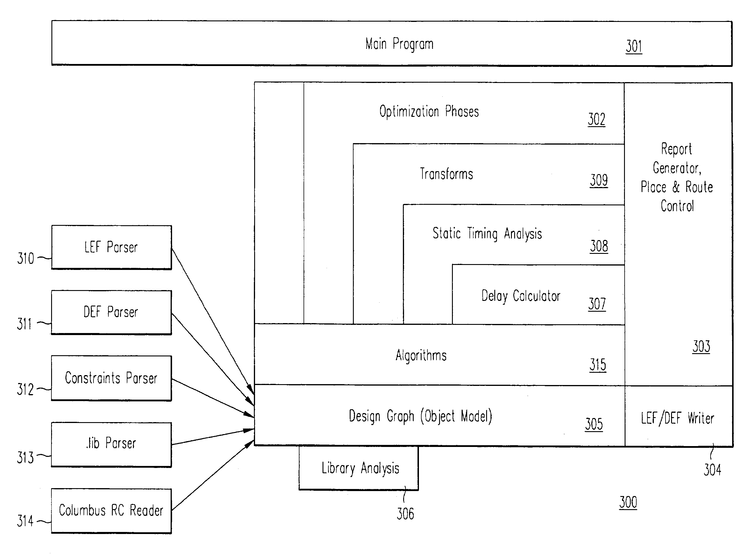
[0063]The present invention provides a design tool and a method for optimizing a standard-cell based integrated circuit after placement and routing are performed, without requiring complete re-synthesis of the integrated circuit design. The present invention optimizes the integrated circuit design based on accurate extraction and modeling of the interconnect network.

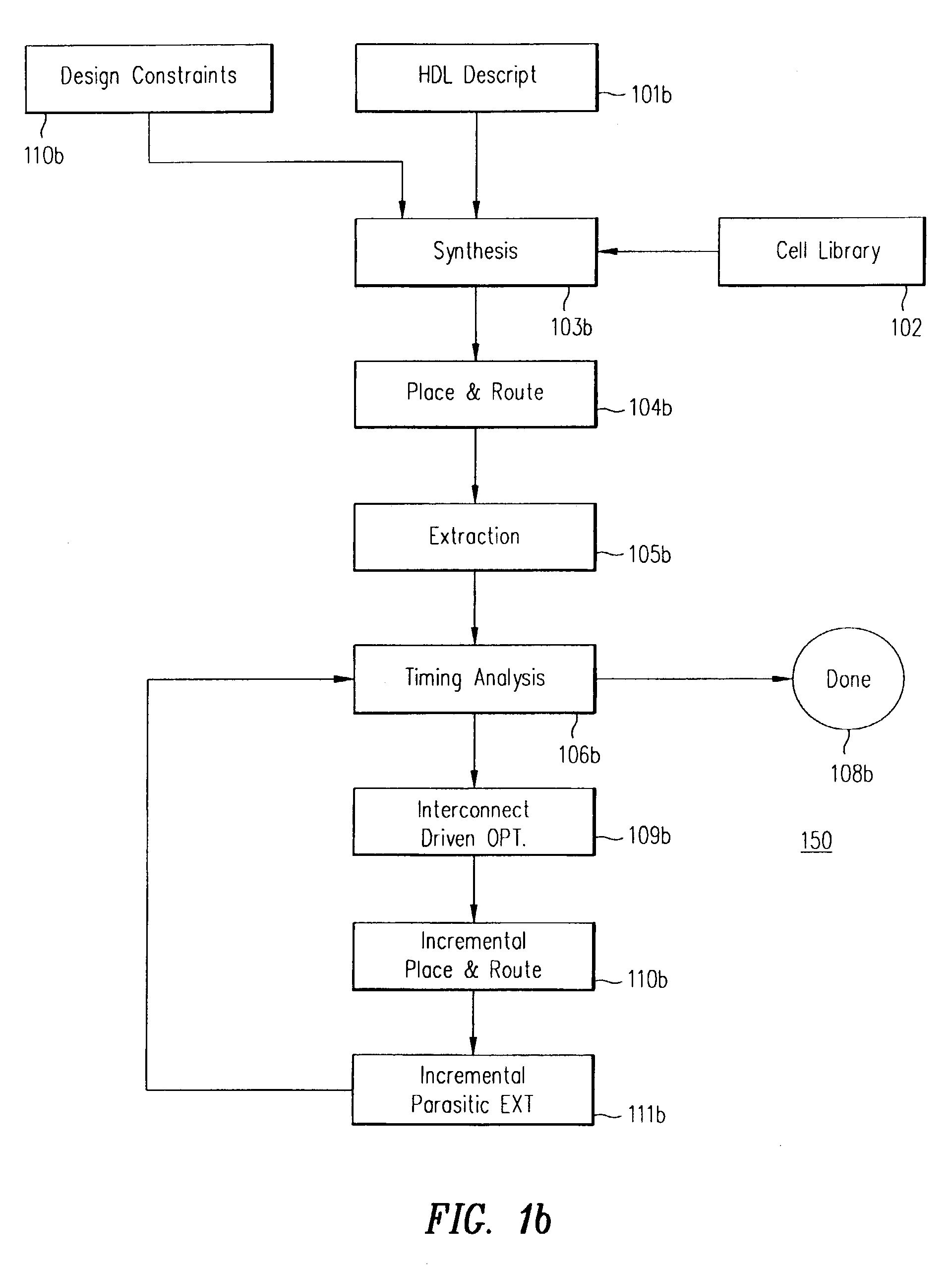
[0064]FIG. 1b shows an overview of design flow 150 in one embodiment of the present invention. Unlike the prior art, in the present invention, the integrated circuit design steps of synthesis, initial placement and initial routing are not re-iterated. Instead, modifications to the physical design are performed incrementally. After completing HDL description, synthesis, place and route, extraction and timing analysis steps 101b–106b, which can be substantially the same as corresponding steps 101–106 of FIG. 1a, the timing problems uncovered by timing analysis step 106b are addressed by an interconnect optimization step 10...


PUM


Abstract

A method and an apparatus are provided for post-layout optimization of an integrated circuit. In one instance, only local transformations accomplished by incremental changes to placement and routing are provided, so as to avoid the costly design iteration loop that requires re-synthesis, re-place and re-route. Optimization can be provided in multiple optimization phases each accomplishing a specified set of transformations. Static timing analysis is performed at the end of each set of local transformations to determine if further optimization steps are required. In one instance, the physical design is first scanned for mismatch between drivers and loads. Then, in a second optimization phase, “hot spots” in the physical design are identified for local transformation using a “bidirectional combinational total negative slack” (BCTNS) algorithm. In subsequent phases, optimization based on meeting setup times and hold times in a critical path are performed.

Description

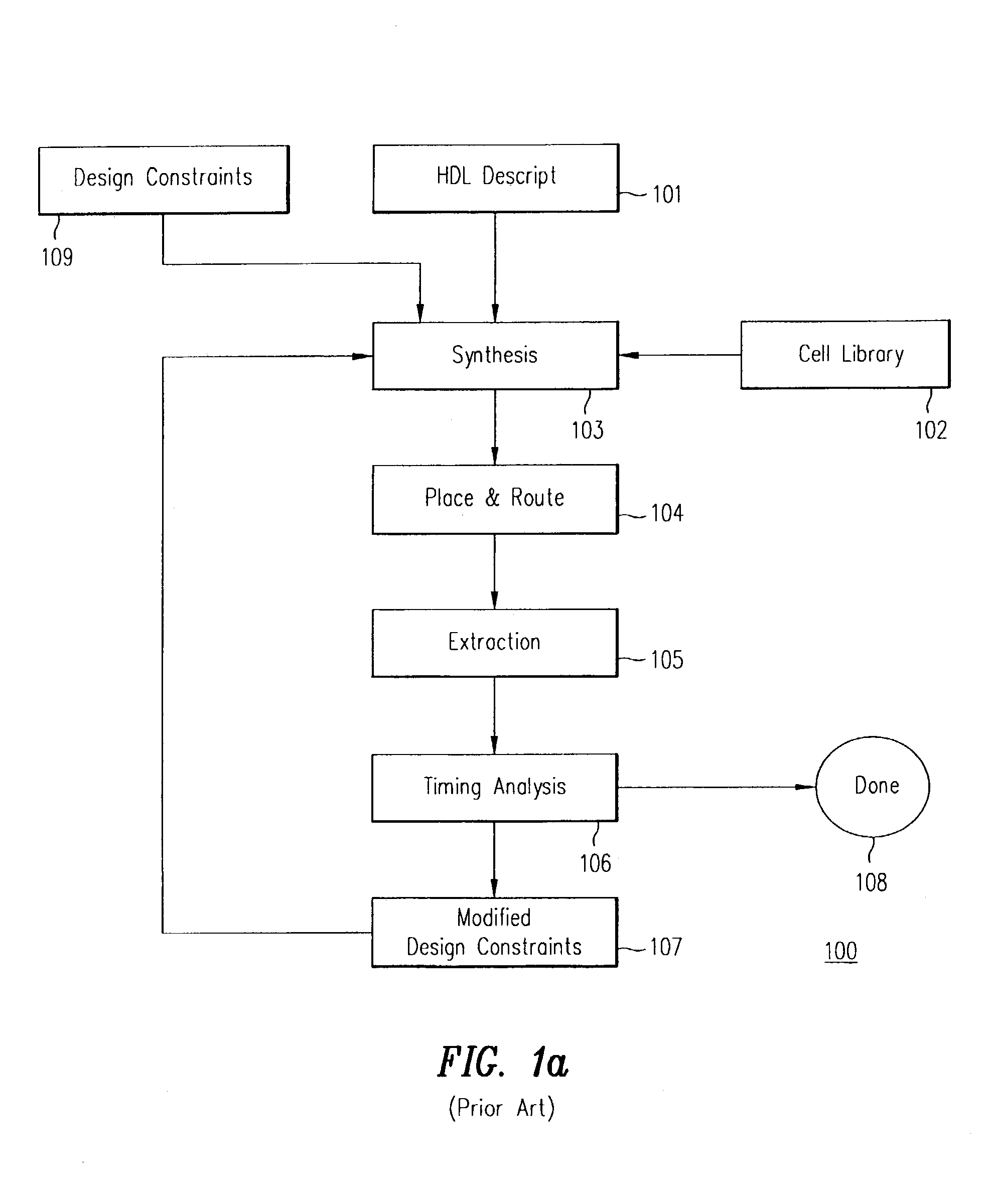
[0001]This application is a divisional application of, and claims priority to, U.S. patent application, entitled “METHOD AND APPARATUS FOR INTERCONNECT-DRIVEN OPTIMIZATION OF INTEGRATED CIRCUIT DESIGN,” Ser. No. 09 / 516,489, filed on Mar. 1, 2000, now U.S. Pat. No. 6,591,407 and assigned to Sequence Design. Inc., which is also the Assignee of the present application.BACKGROUND OF THE INVENTION[0002]1. Field of the Invention[0003]The present invention relates to a tool for integrated circuit design. In particular, the present invention relates to a tool for optimizing the physical design of a standard cell-based integrated circuit for performance.[0004]2. Discussion of the Related Art[0005]A standard cell-based integrated circuit is designed using a library of building blocks, known as “standard cells.” Standard cells include such elements as buffers, logic gates, registers, multiplexers, and other logic circuits (“Macros”).[0006]FIG. 1a shows a typical design process or “flow”100 tha...

Claims


Application Information

Patent Timeline
IPC IPC(8): G06F17/50
CPCG06F17/505G06F17/5068G06F30/39G06F30/327G06F2119/12G06F30/3315
Inventor KAUFMAN, DOUGLASALMUSA, HAZEMSRINIVAS, VINAYORGAN, DONALD V.KE, LARRYLI, WEISINGH, JAPINDERMATHEWS, ROBERT
Owner ANSYS
Learn More