
Decoding device having a turbo decoder and an RS decoder concatenated serially and a method of decoding performed by the same

a decoding device and a technology of rs decoding, which are applied in the direction of coding, code conversion, fault response, etc., can solve the problems of increasing power consumption for decoding, increasing the possibility of error correction, and increasing the decoding time. achieve the effect of optimizing error correction performan

Active Publication Date: 2007-05-22
SAMSUNG ELECTRONICS CO LTD
View PDF10 Cites 21 Cited by
  • Summary
  • Abstract
  • Description
  • Claims
  • Application Information

AI Technical Summary

Benefits of technology

[0015]The present invention is made to overcome the above-identified problems and accordingly it is an object of the present invention to provide a decoding device which prevents unnecessary and insufficient decoding of signals which are encoded by the RS encoder and a turbo encoder, and which optimizes error correction performance.
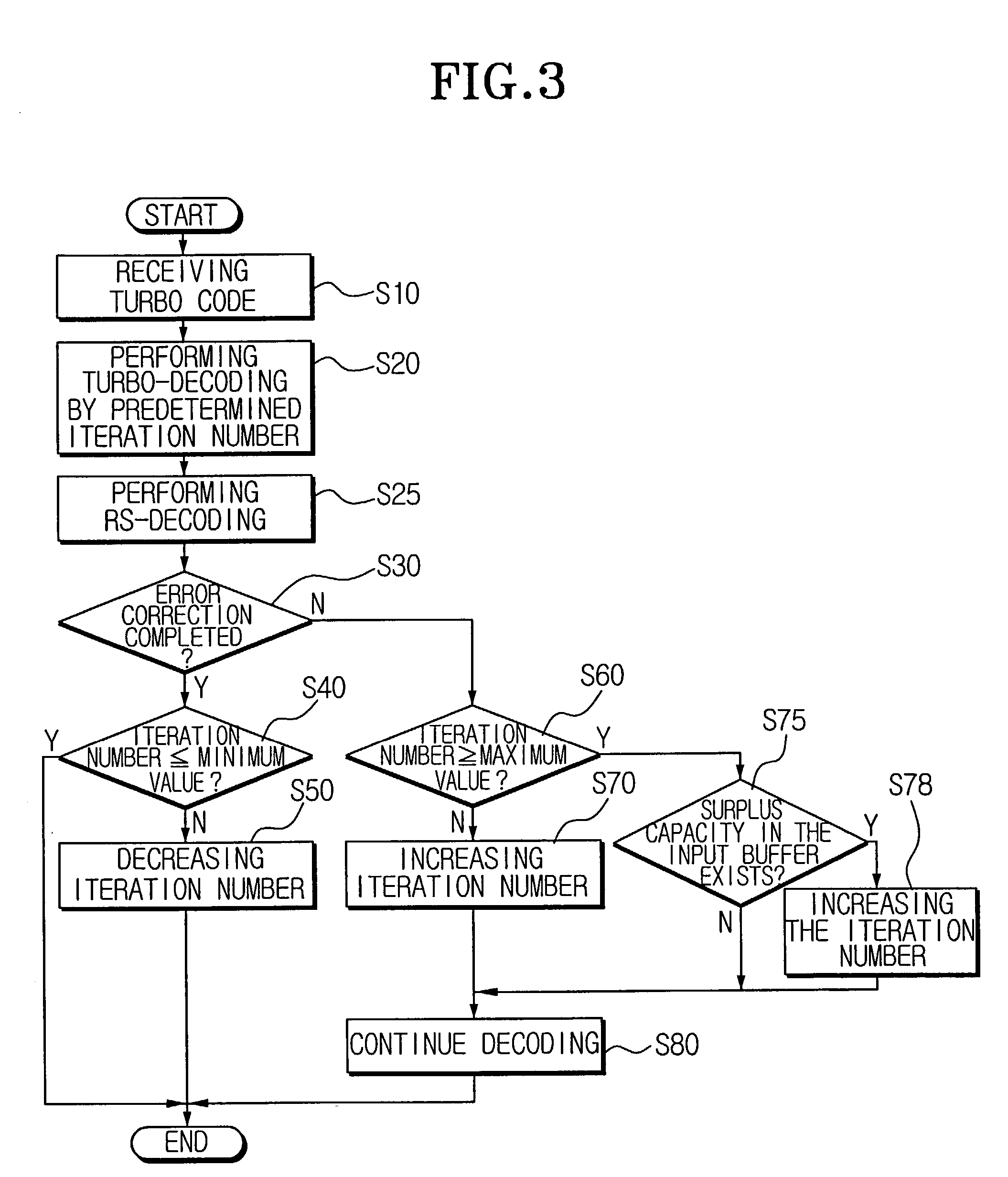
[0018]The controller reduces the iteration number where the completion signal occurs in the second decoder as a result of the second decoding of the turbo decoded inputs by the turbo decoder as many times as the iteration number and increases the iteration if the completion signal is not received. Accordingly, the decoding performance becomes optimized by the adaptive changes in the iteration number according to the channel condition.
[0020]The decoding device according to the present invention further comprises an input buffer which temporarily stores input data to the turbo decoder and an output buffer which temporarily stores an output of the RS decoder. The controller may set the iteration number to be greater than the predefined maximum value if the input buffer has storage capacity available or the output buffer does not have storage capacity available. Accordingly, error correction with better performance is possible without unnecessary time delay.

Problems solved by technology

As the iteration number gets greater, the possibility of error correction increases.
However, if the iteration number is too great, a decoding time becomes long and power consumption for decoding increases.
However, this method may increase the decoding time and power consumption as the unnecessary iterative decoding may be performed even though an error is sufficiently corrected.
Additionally, this method has a problem that the desired error correction performance may not be achieved as the iterative decoding can be ceased although the error correction is not completed.
However, in the method using the CRC, the turbo code should be encoded again according to the CRC method, which may cause a data rate loss and the CRC result may be incorrect.
In addition, the method using the LLR has a difficulty in determining a proper threshold value for ceasing the iteration, and errors may still occur even though the LLR conditions are met.

Method used


Image

  • Decoding device having a turbo decoder and an RS decoder concatenated serially and a method of decoding performed by the same
  • Decoding device having a turbo decoder and an RS decoder concatenated serially and a method of decoding performed by the same
  • Decoding device having a turbo decoder and an RS decoder concatenated serially and a method of decoding performed by the same

Examples


Embodiment Construction

[0026]Reference will now be made in detail to the present embodiments of the present invention, examples of which are illustrated in the accompanying drawings, wherein like reference numerals refer to like elements throughout.

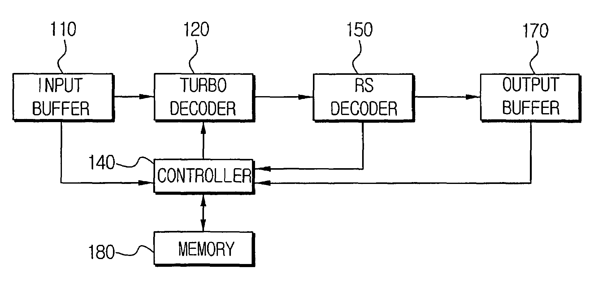
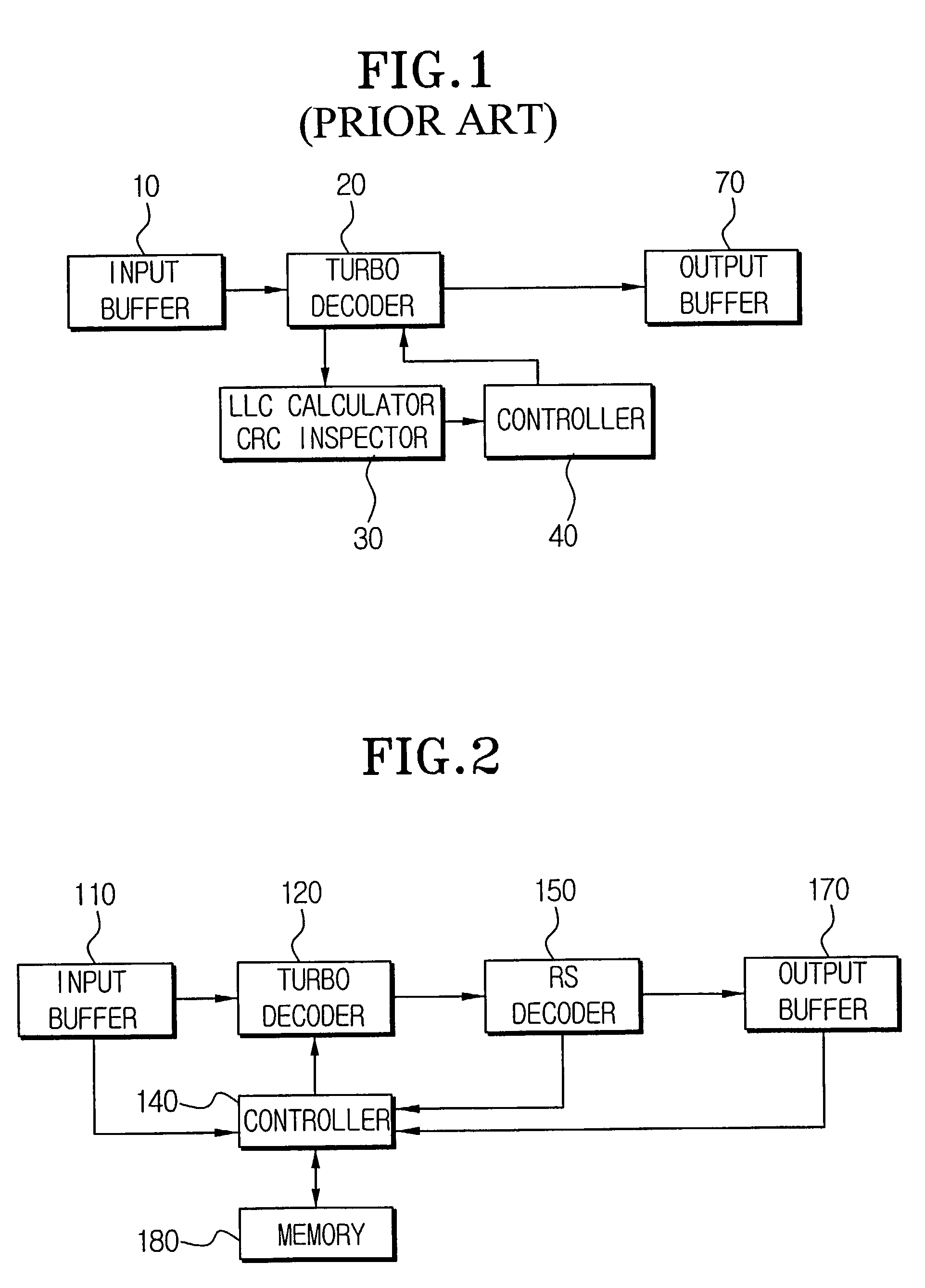
[0027]The decoding device according to the present invention decodes signals which are encoded by an RS encoder and a turbo encoder. In other words, a signal transmitter has an RS encoder and a turbo encoder and accordingly the signals to be transmitted are encoded by the RS encoder to be a block code and then encoded again by the turbo encoder.

[0028]FIG. 2 is a block diagram of the decoding device according to an embodiment of the present invention. The decoding device comprises an input buffer 110, a turbo decoder 120, an RS decoder 150, an output buffer 170, a controller 140, and a memory 180.

[0029]The input buffer 110 temporarily stores the input signals (input data) and the stored signals are provided to the turbo decoder 120. The output buffer 170 tempora...


PUM


Abstract

A decoding device having a turbo decoder and an RS decoder concatenated serially and a method of decoding performed by the same. A turbo decoder decodes received data of a channel and an RS decoder RS decodes the turbo decoded data. A controller controls the turbo decoder to iteratively turbo-decode the data according to a number of iterations determined by a stored iteration number and to cease the turbo decoding if an error correction completion signal is received from the RS decoder. The controller decreases the iteration number for a next frame of the data if the completion signal is received within the predetermined number of iterations and increases the iteration number for a next frame if the completion signal is not received within the predetermined number of iterations. The iteration number is changeable within maximum and minimum limits and may exceed the maximum limit in special cases.

Description

CROSS REFERENCE TO RELATED APPLICATIONS[0001]This application claims the benefit of Korean Application No. 2002-1813 filed Jan. 11, 2002 in the Korean Industrial Property Office, the disclosure of which is incorporated herein by reference.BACKGROUND OF THE INVENTION[0002]1. Field of the Invention[0003]The present invention relates to a decoding device having a turbo decoder and an RS decoder serially concatenated, and more particularly, to a device for decoding a signal which has undergone both an RS encoding and a turbo encoding, and a decoding method thereof.[0004]2. Description of the Related Art[0005]Generally, in order to correct an error on a channel, a wireless digital communication system uses a method of adding an error correction code in a transmitting terminal and a method of correcting the error in a receiving terminal. One of the coding methods used for the error correction is a turbo code. The turbo code is employed for a channel in need of a high data rate such as CDM...

Claims


Application Information

Patent Timeline
IPC IPC(8): H03M13/00G06F11/10H03M13/15H03M13/29H03M13/35H04L1/00
CPCH03M13/151H03M13/29H03M13/2966H03M13/2975H03M13/3707H03M13/1515
Inventor KIM, KI-BO
Owner SAMSUNG ELECTRONICS CO LTD
Learn More