
Method and device for optical detection of the position of an object

a technology of optical detection and position detection, applied in the direction of measuring devices, biological neural network models, instruments, etc., can solve the problems of unsuitable for such doing, undesigned, and relatively expensive devices, and achieve the effects of optimizing the coverage of the detection zone, simple, compact and inexpensiv

Inactive Publication Date: 2007-05-22
H2I TECH A DIRECTOIRE & CONSEIL DE SURVEILLANCE
View PDF13 Cites 41 Cited by
  • Summary
  • Abstract
  • Description
  • Claims
  • Application Information

AI Technical Summary

Benefits of technology

[0037]In practice, and in particular for a plane zone of rectangular outline, the result is that there is no need to place photoemitters and photoreceivers along a short side and along a long side of the outline. It becomes possible to place emitters along a curved line and / or at spacing that varies. It is also possible to place some of the emitters outside the outline of the zone and to place other emitters inside said outline. The same applies to the receivers.
[0056]The invention provides a method and a device for detecting position that is very simple, compact, and inexpensive.

Problems solved by technology

French patent FR 2 443 173 describes a keyboard having moving keys and a plurality of light sources and light sensors enabling key depressions to be detected; that keyboard is expensive since it requires large numbers of mechanical components and of optoelectronic components; it is also complex because of the way the light sources and sensors are spread throughout the zone in which the keys are situated.
A drawback of those devices results from the fact that they require optical components (sources, detectors, and where necessary reflectors) to be placed in substantially distributed manner around the perimeter of the input zone (or monitored zone), and for this to be done with sufficient geometrical accuracy to avoid falsifying the calculations performed on the basis of data representative of the signals delivered by the detectors in order to determine the position in the input zone of an obstacle (finger, etc.) serving to define the data selected by the user.
As a result, those devices remain relatively expensive.
That system is not designed to determine the position of an article in the monitored zone; nor is it suitable for so doing since neither the emitters nor the detectors cover the entire zone that is to be monitored.
The use of diffraction fringes from a laser beam is not applicable to detecting the position of a finger in a zone of determined outline insofar as the presence of a finger does not lead to the presence of diffraction fringes.

Method used


Image

  • Method and device for optical detection of the position of an object
  • Method and device for optical detection of the position of an object
  • Method and device for optical detection of the position of an object

Examples


Embodiment Construction

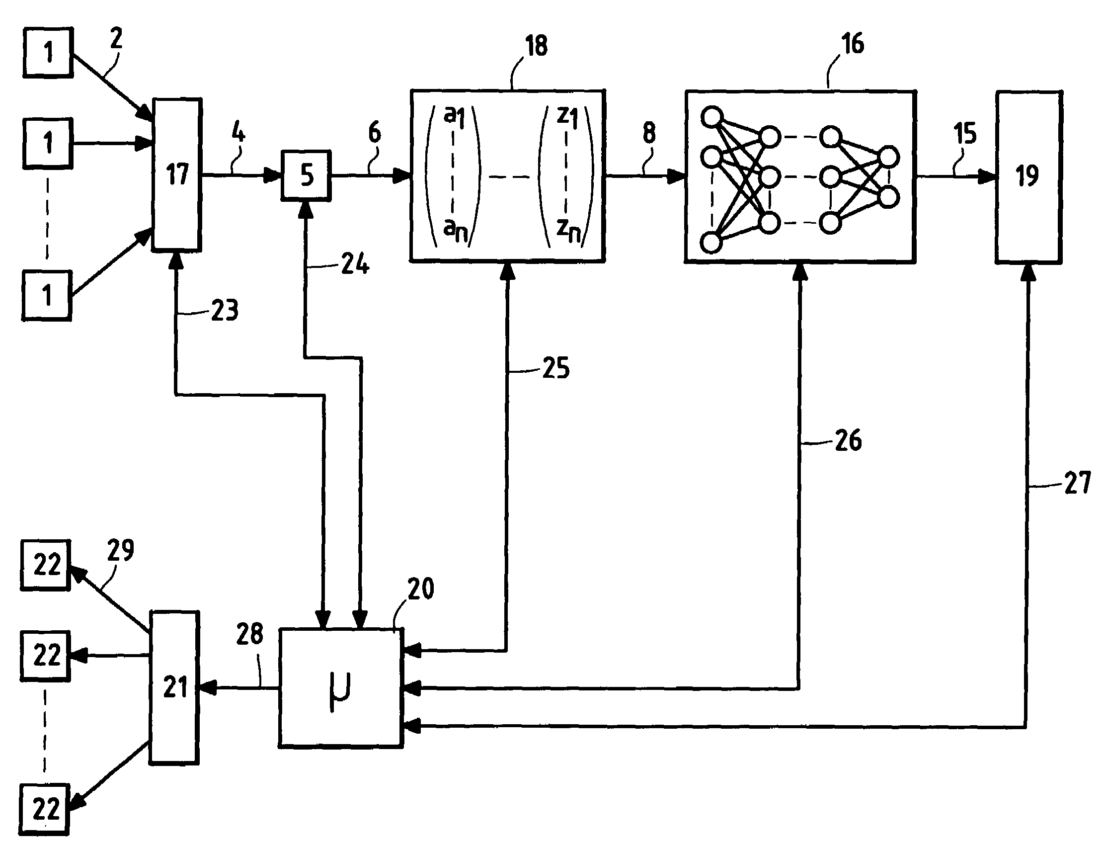
[0063]With reference to FIGS. 3 and 4, the invention applies in particular to determining the position of a member such as a user's finger or a writing tool or pointer such as a stylus which is brought close to or put into contact with a zone 30 of a substrate 37. The rectangular zone 30 is defined by four rectilinear segments 31, 32, 33, and 34 that are orthogonal in pairs. In FIG. 3, the zone 30 is subdivided into four rectangular subzones 36 defined by said segments and also by two segments 34 and 35 in a cross-configuration. Four alphanumeric symbols “1”, “2”, “3, and “4” are written on the substrate 37 in respective ones of the subzones 36, thereby constituting four predetermined data items that can be input by an operator.

[0064]To this end, the terminal 45 (FIG. 3) has three photodiodes 1 disposed in a regularly spaced-apart configuration along an axis 40 parallel to the segments 32, 34, and 44, and to the short sides 39 of the substrate 37. The terminal also has four LEDs 22 ...


PUM


Abstract

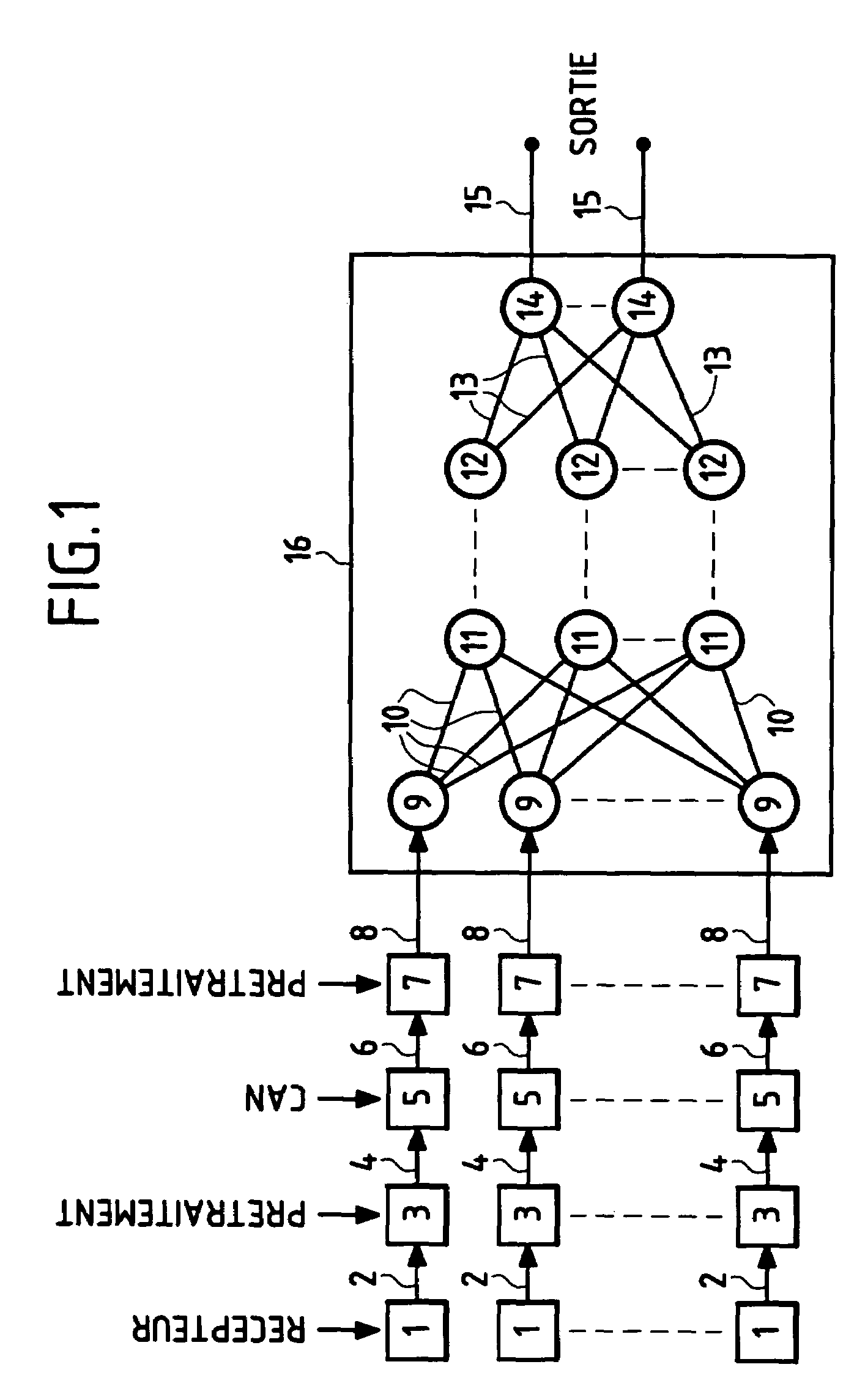
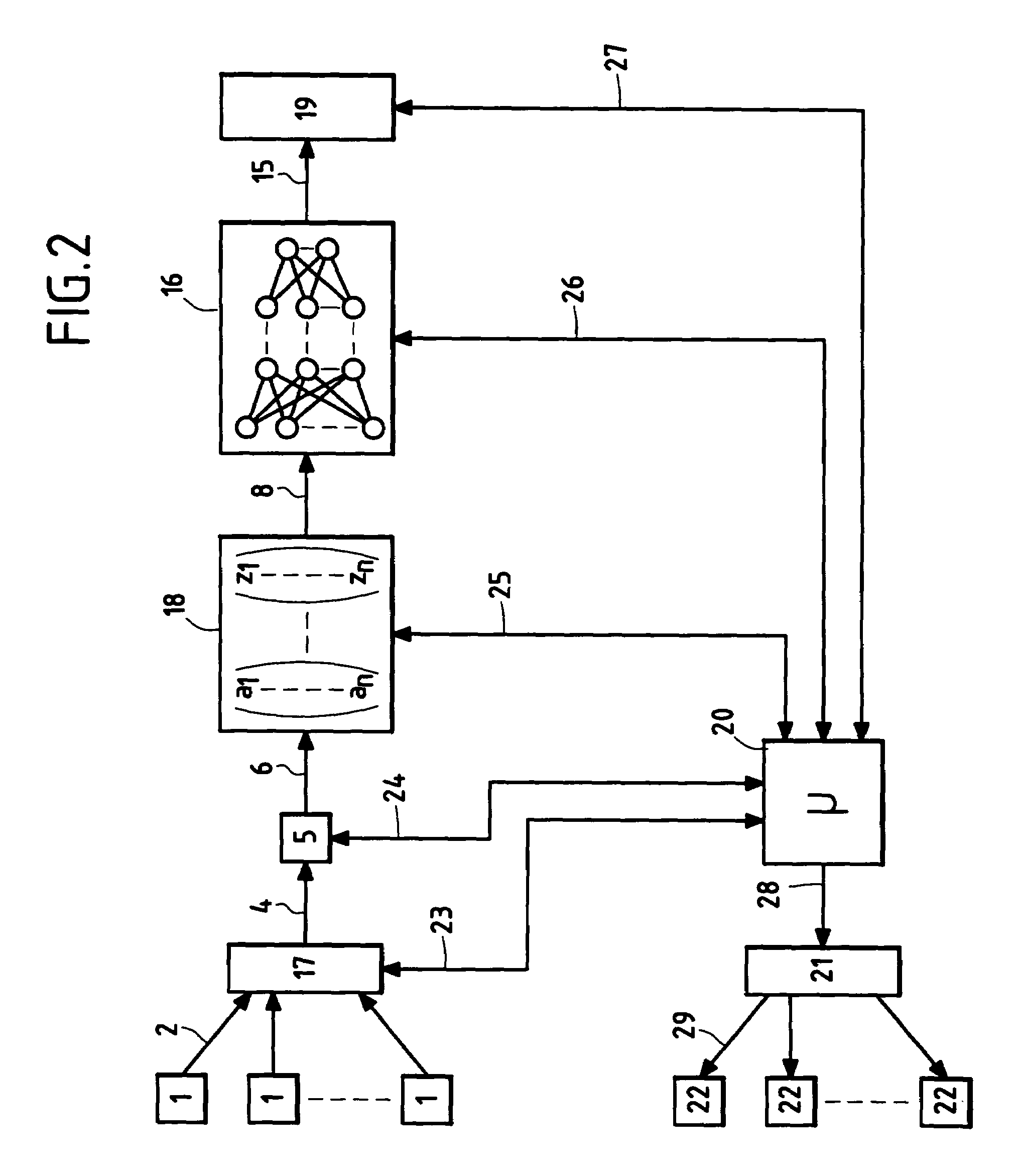
The present invention relates to a method and to a device enabling data to be input, and also to an optical system for detecting the position of an article or a member and suitable for being used (or incorporated) in such a method (or device). The technical field of the invention is that of making keyboards and similar devices enabling manual input of data for processing by a digital computer. The method of the invention for determining the position of an article in a zone uses the steps of structuring a neural network by training, applying data to the input of the structured neural network, the data being the result of converting signals delivered by a plurality of detectors sensitive to illumination of said zone, and determining the position of the article in the zone as a function of at least one data item output by the structured neural network.

Description

PRIORITY CLAIM[0001]This is a U.S. national stage of application No. PCT / FR02 / 02111, filed on 19 Jun. 2002. Priority is claimed on that application and on the following application(s): Country: France, Application No.: 01 / 08186, Filed: 21 Jun. 2001.FIELD OF THE INVENTION[0002]The present invention relates to a method and to a device enabling data to be input, and also to a system for optically detecting the position of an article or a member and suitable for being used or incorporated in such a method or device.[0003]The technical field of the invention is that of making keyboards and similar devices enabling manual input of data for processing by a digital computer.BACKGROUND OF THE INVENTION[0004]Numerous optical systems exist that are used for detecting the position of a member or an article in order to input data, and in particular alphanumeric data.[0005]French patent FR 2 443 173 describes a keyboard having moving keys and a plurality of light sources and light sensors enablin...

Claims


Application Information

Patent Timeline
Patent Type & Authority Patents(United States)
IPC IPC(8): G01B11/14H03K17/78H03K17/94G06N3/067
CPCH03K17/94H03K17/943G06N3/067
Inventor CAVALLUCCI, GILLES
Owner H2I TECH A DIRECTOIRE & CONSEIL DE SURVEILLANCE
Learn More