
Frequency converter for different mains voltages

a technology of frequency converter and mains voltage, which is applied in the direction of ac-dc conversion, single-phase induction motor starter, power electronics conversion efficiency, etc., can solve the problems of voltage drop, increase the current sink of mains, etc., and achieve the effect of increasing the operational reliability, and reducing the output power of the inverter

Inactive Publication Date: 2007-05-22
DANFOSS DRIVES
View PDF17 Cites 142 Cited by
  • Summary
  • Abstract
  • Description
  • Claims
  • Application Information

AI Technical Summary

Benefits of technology

[0010]Based on the above, the object of the invention is to design a general purpose frequency converter, which electrically can adapt, or can easily be adapted, to its surroundings.
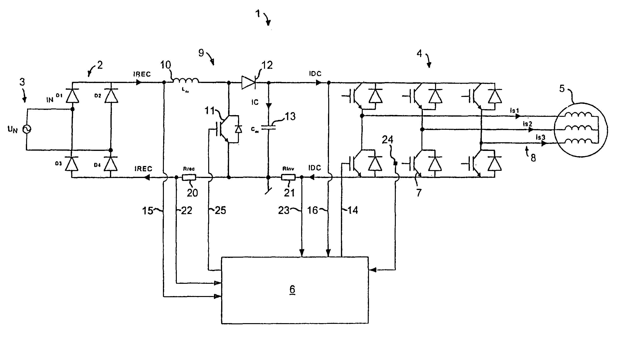
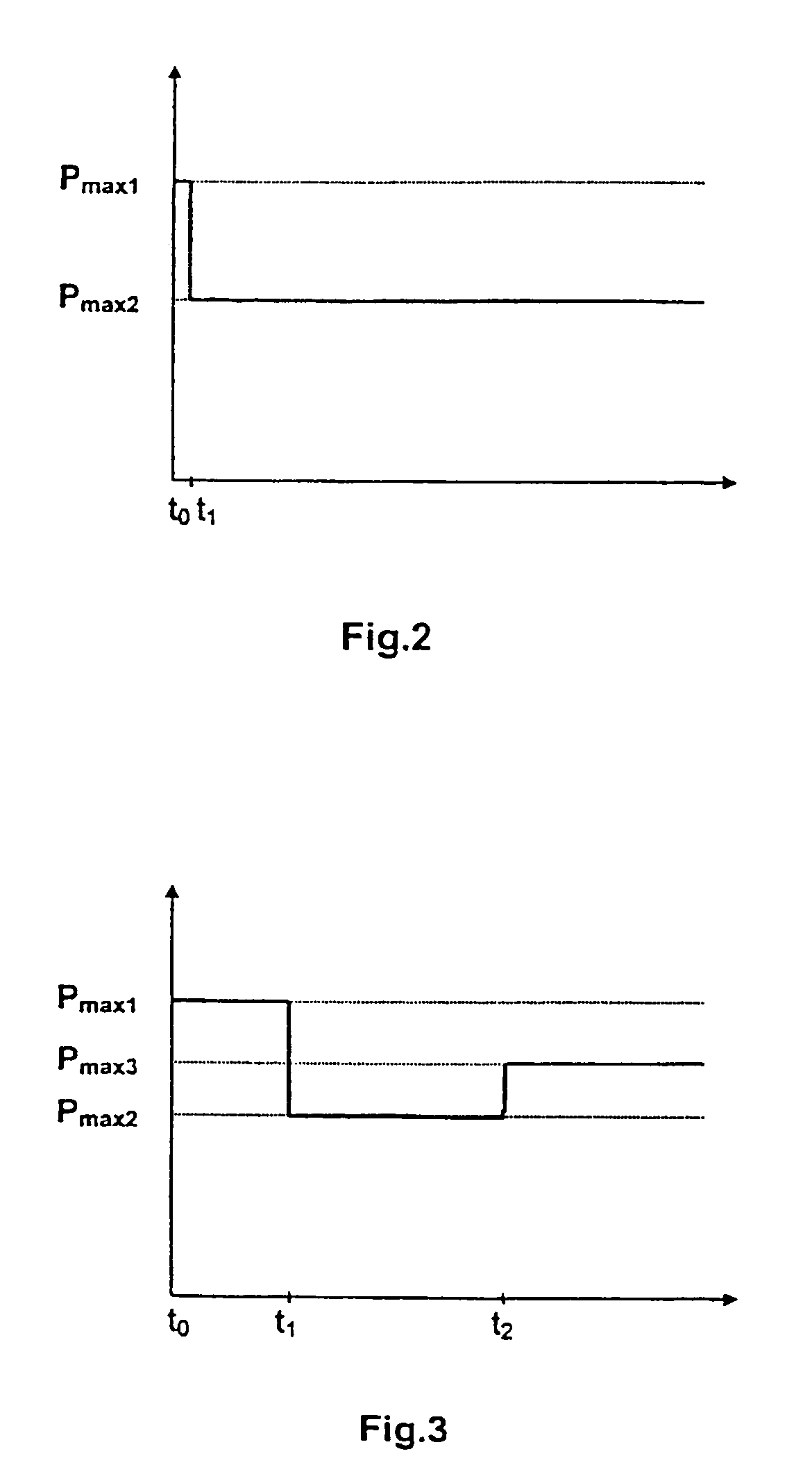
[0011]According to the invention, this task is solved by a method where a DC / DC converter placed between a rectifier and an inverter is regulated to output a DC voltage that is kept constant during operation at each one of the several mains voltages, that a limit value signal is compared with one ore more measured or calculated parameters, that a control device limits the maximum output power by reducing the motor frequency generated by the inverter, and that the frequency converter, during a limitation of an output power of from the inverter, controls the speed of the electric motor within a power range up to the limited maximum output power.

Problems solved by technology

Imagining that a frequency converter according to the state of the art is connected between a motor and a weak mains, and the weak mains has a lower voltage than expected, this will cause an increased current sink from the mains, which again results in a voltage drop, etc.

Method used


Image

  • Frequency converter for different mains voltages
  • Frequency converter for different mains voltages
  • Frequency converter for different mains voltages

Examples


Embodiment Construction

[0050]The frequency converter 1 has a rectifier 2 that is connected to a supply mains 3, which can have one of the standard voltages 115V, 230V or any other value. In the following, “nominal voltage” means the specified value, whereas the “actual voltage” means the real, available voltage. The frequency converter is built into a washing machine, and the supply mains is here shown as one-phase mains, but in principle also more phases are possible. A three-phase motor 5 is connected to an inverter 4, and the inverter is controlled by a control device 6. The control device contains memory elements (RAM) and can be made as a micro controller, DSP (Digital Signal Processor) or ASIC (Application Specific Integrated Circuit) with integrated or external memory. In a known manner the rectifier converts the alternating voltage of the supply mains to a direct voltage, which via the power semiconductors 7 of the inverter, for example IGBTs (Insulated Gate Bipolar Transistor), is reconverted to ...


PUM


Abstract

The invention is directed to controlling an electric motor by means of a frequency converter. The frequency converter can be connected to one of several different mains voltages. According to the present invention, the maximum output power of the frequency converter, is limited when the actual mains voltage is lower than the maximum nominal mains voltage, for which the frequency converter is designed, and during the limitation the frequency converter controls the speed of the motor within a power range up to a limited maximum output power. This gives a genuine multi-voltage unit, which can be connected to a wide range of mains voltages.

Description

CROSS-REFERENCE TO RELATED APPLICATIONS[0001]This application is entitled to the benefit of and incorporates by reference essential subject matter disclosed in International Application No. PCT / DK02 / 00785 filed on Nov. 21, 2002, Danish Patent Application No. PA 2001 01750 filed on Nov. 23, 2001 and Danish Patent Application No. PA 2001 01751 filed on Nov. 23, 2001.FIELD OF THE INVENTION[0002]The invention concerns a frequency converter, which can be connected to one of several different mains voltages, and a method for speed control of an electric motor by means of a frequency converter.BACKGROUND OF THE INVENTION[0003]Differences in the mains voltages in the USA and Europe increase the production costs, as product differentiation is required. For years, therefore, it has been known to make frequency converters, which can be connected to different mains voltages, see for example U.S. Pat. No. 4,656,571.[0004]However, this gives rise to a problem, when a frequency converter is connec...

Claims


Application Information

Patent Timeline
Patent Type & Authority Patents(United States)
IPC IPC(8): H02P23/00H02P25/00H02P27/04H02M1/00H02M1/10H02M5/458H02M7/5387H02P4/00H02P27/06
CPCF04C28/08H02M1/10H02M5/458H02M7/53873H02P4/00H02P27/047H02P27/06H02M1/32H02M2001/0022H02M2001/0025H02M2001/007H02M1/4225Y02B70/10H02M1/0022H02M1/0025H02M1/007
Inventor SKAUG, KENNETHTOENNES, MICHAELHARVEST, NILS-OLEKROGH, EGONAUPKE, ANDREAS
Owner DANFOSS DRIVES
Learn More