
Child seat

a child seat and car seat technology, applied in the direction of child seats, chairs, pedestrian/occupant safety arrangements, etc., can solve the problem of increasing the load on the newborn's shoulder, and achieve the effect of preventing an impa

Inactive Publication Date: 2007-05-22
COMBI CORP
View PDF23 Cites 55 Cited by
  • Summary
  • Abstract
  • Description
  • Claims
  • Application Information

AI Technical Summary

Benefits of technology

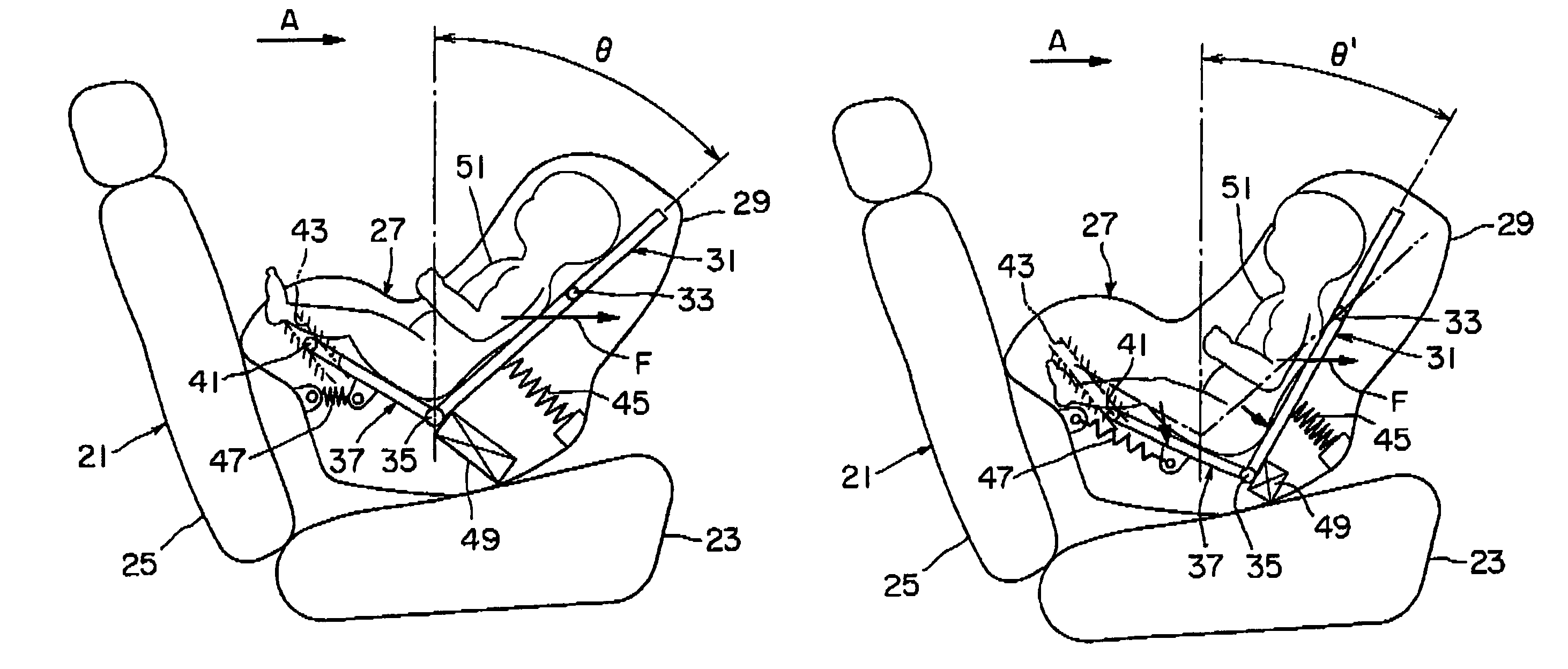
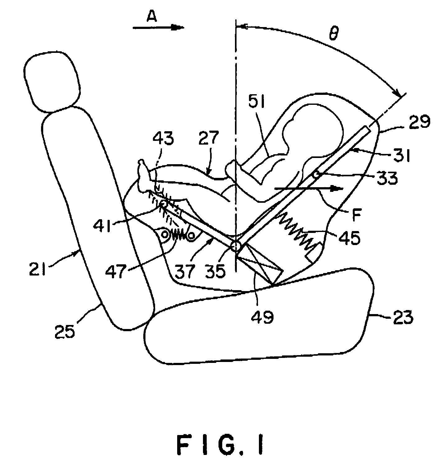
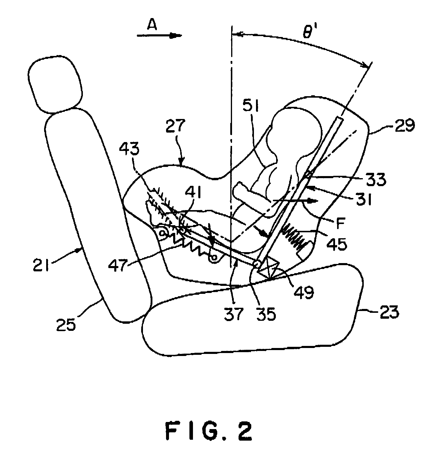
[0006]The first feature of the present invention resides in the provision of a child car seat comprising a child car seat body, a back portion rotatably held in inclination by the child car seat body, a seat portion rotatably connected to a lower part of the back portion and a shock absorbing member arranged between the child car seat body and either one or both of the back portion and the seat portion, wherein the seat portion and the back portion are adapted so as to hold a newborn thereon, and the child car seat is constructed in a manner that when an impact force directing from a front face side of the back portion toward a back face side of the back portion is applied on the newborn, the back portion rotates in its rising direction and the shock absorbing member operates to reduce the impact force applied on the newborn. Accordingly, despite of holding the newborn in a condition where it nearly lies on its back at a normal state, it is possible to prevent an impact from concentrating in a part of the newborn at the time of impact.
[0007]According to the second feature of the invention, a rotation pivot of the back portion is positioned above a gravity center of the newborn. Thus, by making use of an inertia force, it is possible to certainly carry out the rising of the back portion with a simple structure and without requiring a special device.
[0008]According to the third feature of the invention, the back portion is rotatably born by the child car seat body. Therefore, by making use of an inertia force at the maximum it is possible to rotate the back portion, thereby accomplishing the rising of the back portion.
[0011]According to the sixth feature of the invention, the back portion is rotatably born by a bearing member and the bearing member is movably held by the child car seat body. Accordingly, by distributing a part of inertia force to the movement of the bearing member, it is possible to reduce an abrupt rising of the back portion, allowing an impact on the newborn to be decreased furthermore.
[0014]According to the ninth feature of the invention, the shock absorbing member is adapted so as to absorb an impact because of a plastic deformation of the shock absorbing member. Therefore, it is possible to perform a shock absorbing operation exhibiting a high attenuation and an awkward vibration.

Problems solved by technology

In particular, there is a problem that the more the seat is reclined, in other words, the newborn is laid down, the more a load exerted to the newborn's shoulder is increased.

Method used


Image

  • Child seat
  • Child seat
  • Child seat

Examples


second embodiment

[0052]FIG. 3 is a view showing a child car seat 61 in accordance with the present invention. This child car seat 61 differs from the child car seat 27 of FIG. 1 in that the seat portion 37 is supported by a joint part 63 in the child car seat 61 of FIG. 3, while the back portion 31 and the seat portion 37 are normally supported by the urging springs 45, 47 in the child car seat 27. The other constitutions of are similar to those of the child car seat 27, respectively. Therefore, elements identical to those of the child car seat 27 are indicated by the same reference numerals respectively and their overlapping descriptions are eliminated.

[0053]In the constitution as above, when a great inertia force F is applied on the newborn 51 at a vehicle's sudden braking, the back portion 31 is subjected to a rotating force in the counter-clockwise direction about the rotating shaft 33 as a rotating center. Due to this rotating force, a force to the right direction of FIG. 4 is applied to the se...

third embodiment

[0055]FIG. 5 is a view showing a child car seat 71 in accordance with the present invention. This child car seat 71 differs from the child car seats 27, 61 of FIGS. 1 and 3 in that a force mechanism 73 is arranged in a position above the rotating shaft 33 of the back portion 31b. In this child car seat 71, though not shown in FIG. 5, the urging spring 45 and the urging spring 47 of FIG. 1 or the joint part 63 support the back portion 31 and the seat portion 37, respectively and the child car seat 71 is also equipped with the shock absorbing mechanism 49. The operations at the time of receiving an impact are also similar to those of the afore-mentioned child car seats.

[0056]This child car seat 71 with the force mechanism is fixed to the seat 21 of the vehicle by means of a seat belt 75, as shown in FIG. 7A. Then, the seat belt 75 is engaged with a belt guide 77 on a back portion of the child car seat body 29. Inside the belt guide 77, there is provided a switch 81 that drives the abo...


PUM


Abstract

This child car seat includes a child car seat body, a back portion rotatably held in inclination by the child car seat body, a seat portion rotatably connected to a lower part of the back portion and a shock absorbing mechanism arranged between the child car seat body and either one or both of the back portion and the seat portion. The seat portion and the back portion hold a newborn. When an impact force directing from a front face side of the back portion toward its back face side is applied on the newborn, the back portion rotates in its rising direction and the shock absorbing mechanism operates to reduce the impact force applied on the newborn. Consequently, the newborn can be held on the child car seat in a state close to a condition where the newborn lies on its back. Since the back portion stands up at the time of impact, the newborn is capable of receiving the impact through the whole area of a newborn's back.

Description

TECHNICAL FIELD[0001]The present invention relates to a child car seat for reducing an impact force applied on a baby.BACKGROUND OF THE INVENTION[0002]In order to reduce the impact force applied to a passenger at a vehicle collision, generally, it is preferable to make a back face of a seat nearly perpendicular thereby receiving an impact by a back of the passenger.[0003]However, when a youth, particularly, a newborn (child) is placed on a child car seat, an angle between a seat face and a back face of the seat is increased as much as possible so that the newborn can lie on its back in the seat because the neck of the newborn is not firm yet. Particularly, when the child weighing less than 10 kg is placed, the child car seat is held backward to a vehicle traveling direction and further, the newborn's body is fixed on the child car seat with a belt.[0004]When an impact acts on the front part of a vehicle with the seat fixed in the above way, the newborn's shoulder is subjected to a c...

Claims


Application Information

Patent Timeline
Patent Type & Authority Patents(United States)
IPC IPC(8): A47D1/10B60N2/28B60N2/42B60R22/10
CPCB60N2/2806B60N2/2863B60N2/2884
Inventor YAMAZAKI, KOJIROYANAKA, HIDENORIWASHIZUKA, MITSURU
Owner COMBI CORP
Learn More