
UAV recovery system

a technology for uavs and recovery systems, which is applied to unmanned aerial vehicles, vehicles, aircraft, etc., can solve the problems of difficult to safely land a uav on the deck of a ship, difficult to recover a uav, and difficult to safely land a uav on the ship deck, etc., so as to reduce the risk of damage to the wings and other parts of the uav, no time loss, and little deck space

Active Publication Date: 2007-05-22
LOCKHEED MARTIN CORP
View PDF27 Cites 124 Cited by
  • Summary
  • Abstract
  • Description
  • Claims
  • Application Information

AI Technical Summary

Benefits of technology

The invention is a system for retrieving a UAV while it's in flight that avoids some of the drawbacks of prior art systems. The system includes an arresting line, a braking system, a stanchion, and a movable boom that supports the arresting line and the braking system. The movable boom is coupled to a ship's deck or a frame for use over land. The system allows for controlled release of the arresting line, preventing damage to the UAV and allowing for easy access to the crew. The use of a single arresting line instead of a net reduces the risk of damage to the UAV and saves time. The system requires very little deck space and can be used over land or sea.

Problems solved by technology

Recovery is considerably more challenging, however, when the UAV is operating at sea.
Due to the constant sway, roll, pitch and yaw of a ship at sea, it is quite difficult to safely land a UAV on the deck of a ship.
In fact, deck landings are rarely attempted.
This technique has its own drawbacks, including a reasonable likelihood of damage to the UAV and some risk to the recovery crew.
One drawback is that the apparatus disadvantageously requires a substantial amount of deck area.
A second drawback is that a relatively labor-intensive untangling operation is required to free the UAV from the net.
Furthermore, the relatively abrupt stop of a UAV in the recovery net can damage its fragile wings.

Method used


Image

  • UAV recovery system
  • UAV recovery system
  • UAV recovery system

Examples


Embodiment Construction

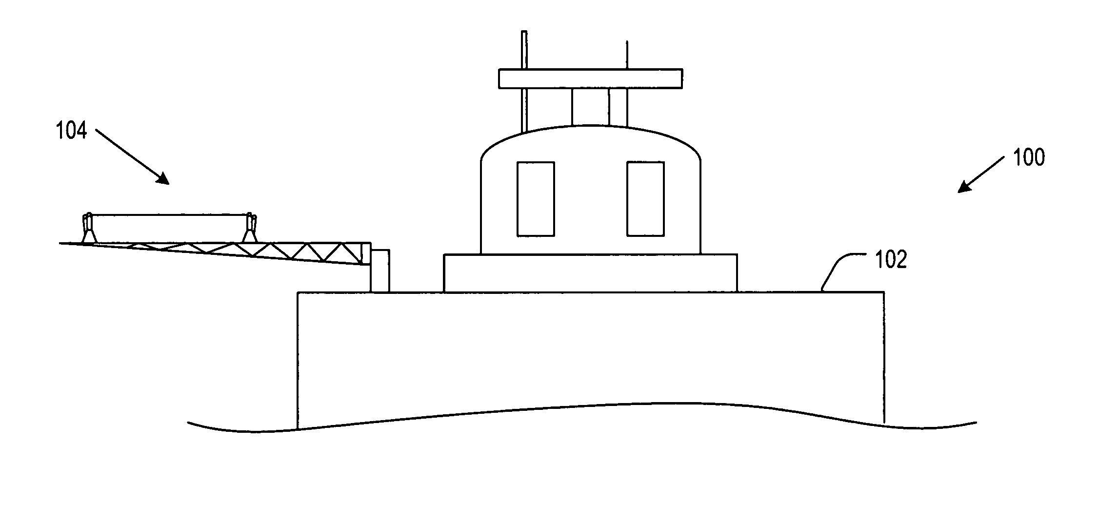
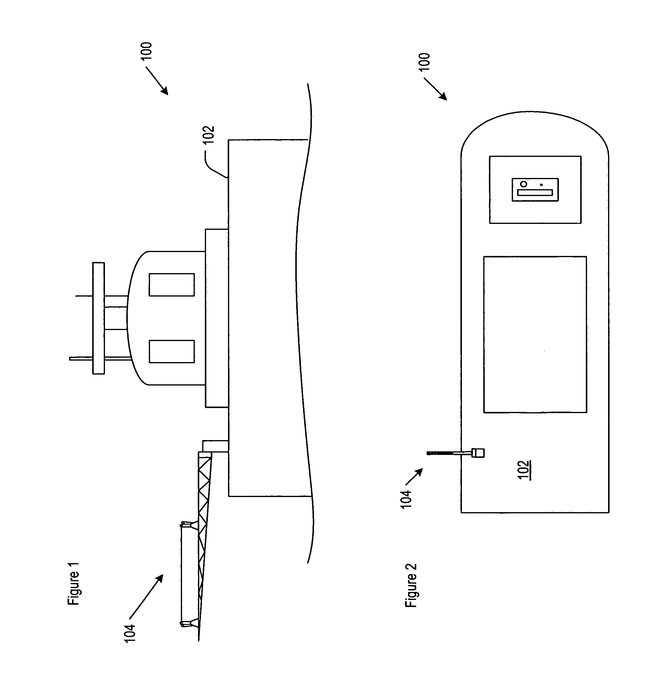
[0022]FIGS. 1 and 2 depict, via respective side and top views, UAV recovery system 104 in accordance with the illustrative embodiment of the present invention. In the illustrative embodiment, the UAV recovery system is mounted to deck 102 of ship 100 to recover UAVs at sea. In some other embodiments, the UAV recovery system, with some modification, is used to recover UAVs over land.

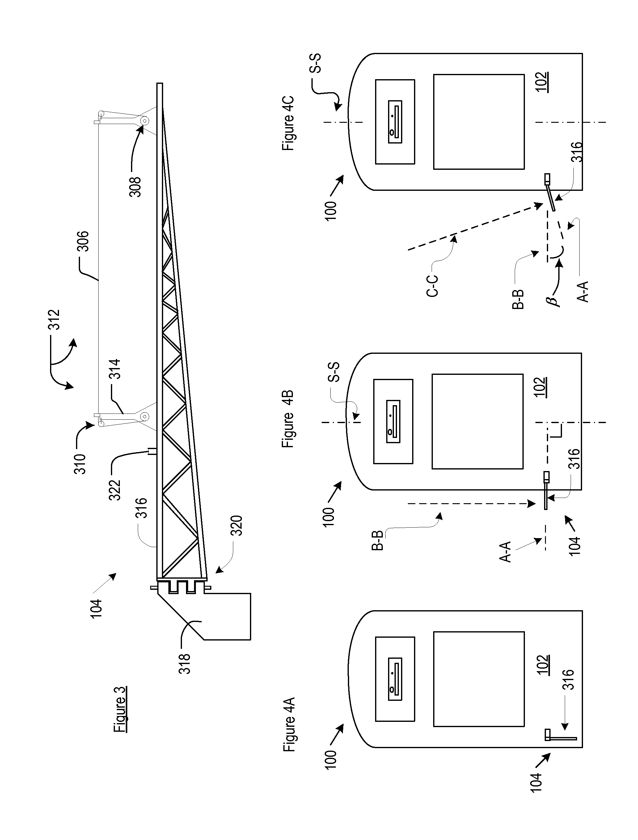
[0023]As depicted in FIG. 3, UAV recovery system 104 includes arresting line 306, braking system 308, stanchion 312, and movable boom 316, mechanically interrelated as shown.

[0024]Stanchion 312, which comprises two upright members 314, supports arresting line 306. The arresting line couples to braking system 308, which is also supported by stanchion 312. Arresting line 306 rides on pulleys 310, which are disposed near the top of upright members 314. As described later in this specification, pulleys 310 facilitate movement of arresting line 306 in conjunction with the UAV recovery operation.

[0025]Stanchion...


PUM


Abstract

A UAV capture system is disclosed. In the illustrative embodiment, the UAV capture system is coupled to the deck of a sea-faring vessel. The UAV capture system includes a single arresting line that is supported by a stanchion. In the illustrative embodiment, the stanchion is disposed on a rotatable boom.

Description

FIELD OF THE INVENTION[0001]The present invention relates to systems for retrieving unmanned aerial vehicles (“UAVs”).BACKGROUND OF THE INVENTION[0002]The UAV is now widely used for reconnaissance. Characteristically small, inexpensive, and pilot-less (i.e., unmanned cockpit), the UAV is ideal for that purpose.[0003]Notwithstanding its low cost, the UAV is not considered to be a disposable item; recovery is at least attempted after each mission. Recovery is relatively straightforward when the UAV is operating over land. In such situations, the UAV is simply brought down on a makeshift landing field. Recovery is considerably more challenging, however, when the UAV is operating at sea. Due to the constant sway, roll, pitch and yaw of a ship at sea, it is quite difficult to safely land a UAV on the deck of a ship. In fact, deck landings are rarely attempted.[0004]One alternative to the deck landing is the water “landing,” wherein a UAV is simply ditched in the sea. This technique has i...

Claims


Application Information

Patent Timeline
Patent Type & Authority Patents(United States)
IPC IPC(8): B64F1/02
CPCB64F1/02B64C2201/182B64U70/30
Inventor WATTS, MICHAEL A.ROOT, JR., GEORGE RAYMONDADAMSKI, DAVID M.
Owner LOCKHEED MARTIN CORP
Learn More