
Liquid displacement shuttle system and method

a shuttle system and liquid technology, applied in water supply installation, transportation and packaging, container discharging methods, etc., can solve the problems of high pressure pressure flow, large storage capacity, and frequent bottlenecks in loading and unloading times of compressed gas transported in multiple assemblies of pressure vessels, and achieve the effect of greater storage volum

Active Publication Date: 2007-05-22
SEAONE HLDG
View PDF23 Cites 49 Cited by
  • Summary
  • Abstract
  • Description
  • Claims
  • Application Information

AI Technical Summary

Benefits of technology

"The present invention is a system for storing and displacing fluids or gases in multiple vessels. The system uses a liquid-piston to move the stored product between the vessels for evacuation. The system includes multiple storage vessels, a discharge manifold, and separate fluid shuttle circuits. The shuttle circuits have reservoirs and pumps to move the displacement liquid between the vessels. The technical effect of this invention is a more efficient and flexible system for storing and displacing fluids or gases in multiple vessels."

Problems solved by technology

The gains in storage capacity from increasing levels of pressure under which compressed gasses are held come at the cost of discharging large volumes in a desired short period of time.
As a result, the flow of compressed gas transported in multiple assemblies of pressure vessels at high pressures is frequently subject to a bottleneck of prolonged loading and unloading times.
However, such an equal volume would require a large shore mounted supply with recycle facilities in the case of marine transportation.
Such a volume would be impractical to carry on board a ship and require inordinate amounts of motive power.

Method used


Image

  • Liquid displacement shuttle system and method
  • Liquid displacement shuttle system and method
  • Liquid displacement shuttle system and method

Examples


Embodiment Construction

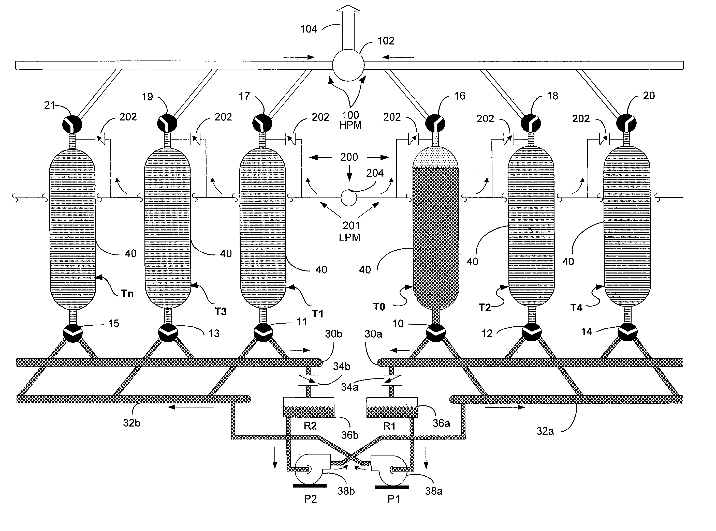
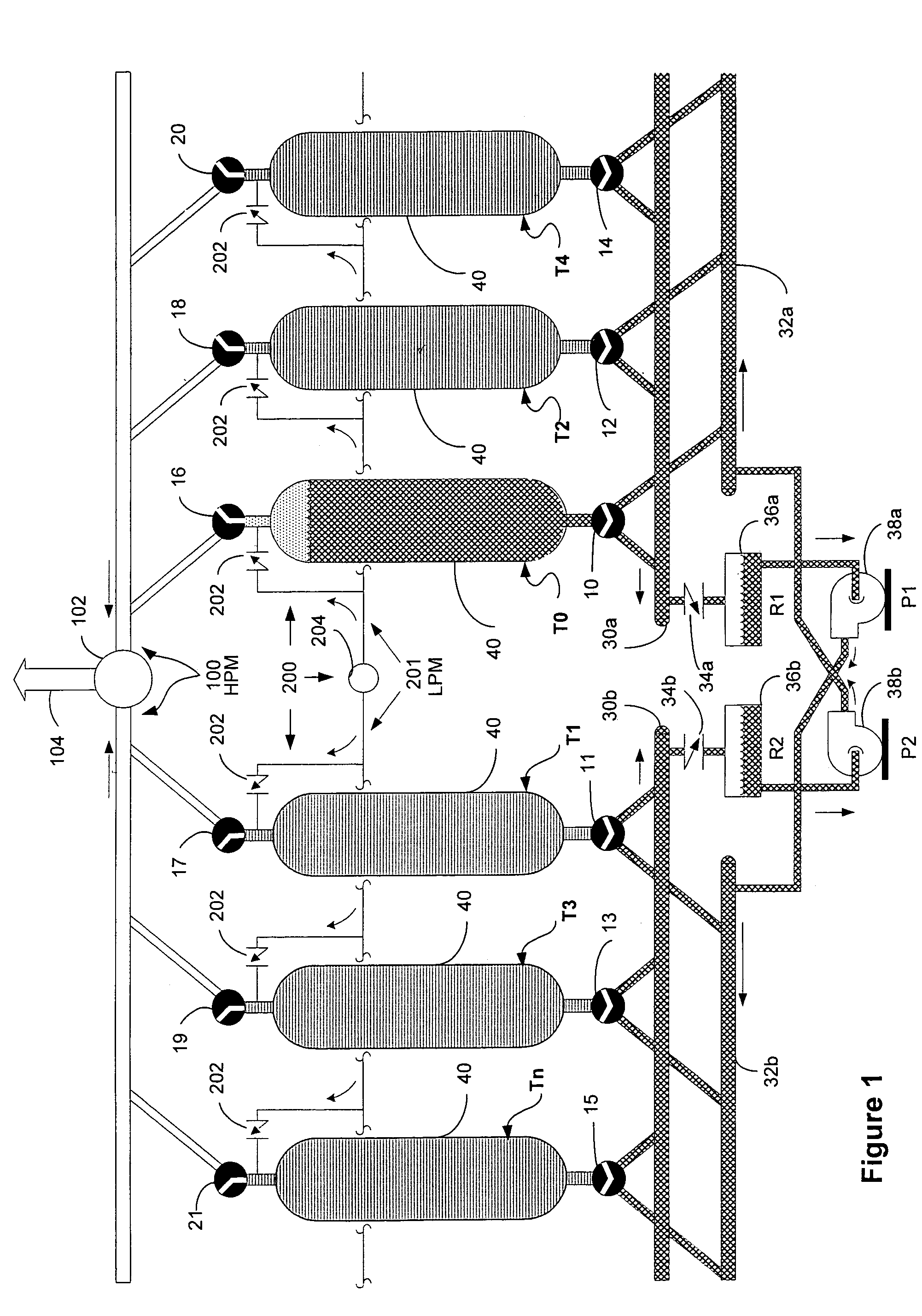
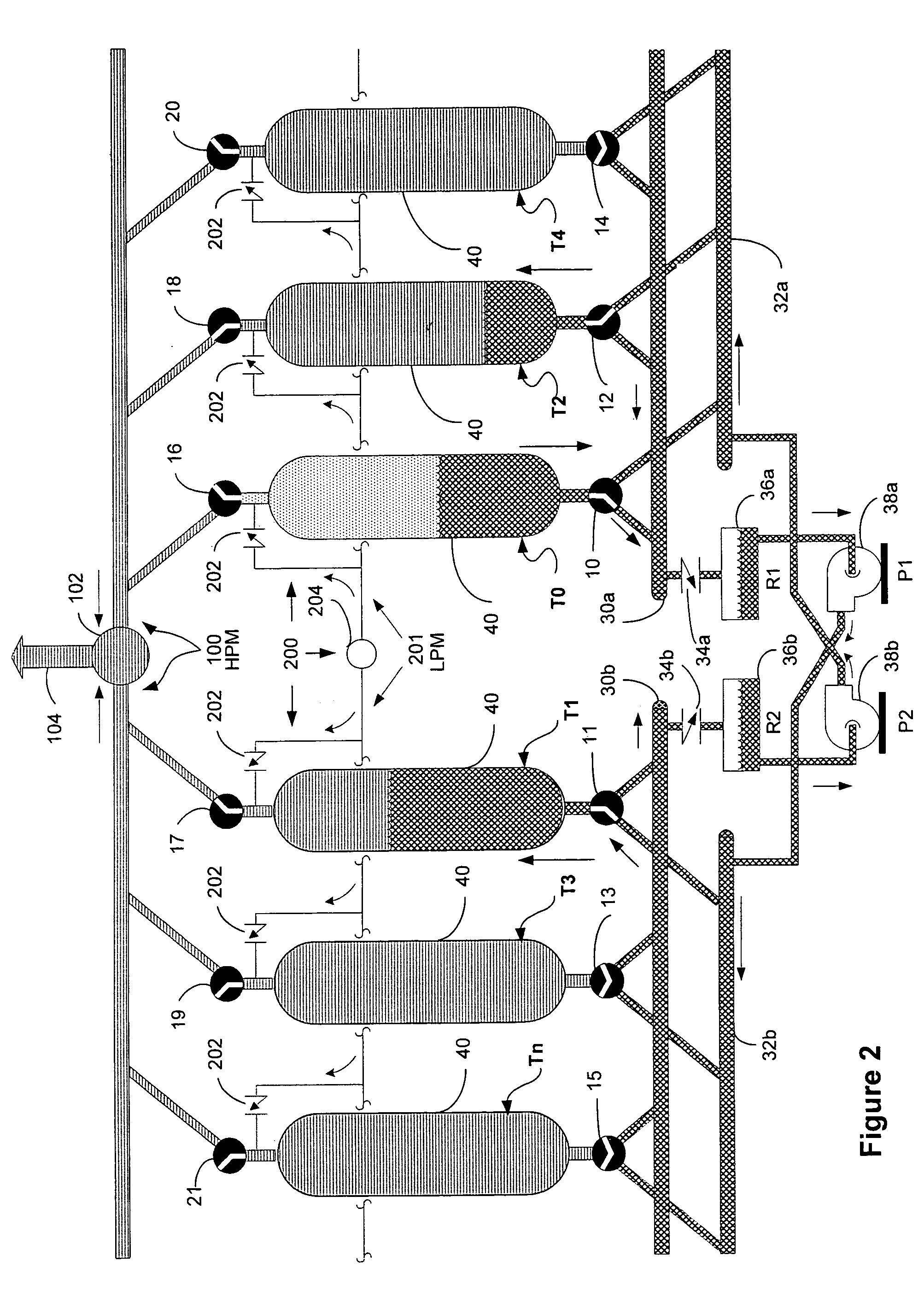
[0014]Turning to the figures, a multi-vessel storage system of the present invention is shown to include a liquid displacement shuttle system. In the liquid displacement shuttle system, use is made of a liquid-piston which is then shuttled to alternate reservoirs for reuse in the next storage vessel or tank in the assembly. In tight spaces, the storage space saved can be used for stored product, and not displacement liquid. Although the liquid displacement shuttle system is depicted and discussed in regard to its use in a compressed or high pressure gas storage system, it is not restricted to use just with compressed gas, and one of skill in the art would understand the liquid displacement shuttle principal being equally suited to moving compatible stored liquids or fluids.

[0015]The present invention reduces the volume of displacement liquid to a fraction of a storage system's volume by shuttling the volume of displacement liquid between alternating storage tanks or banks of storage...


PUM


Abstract

A multi-vessel gas storage system and liquid displacement shuttle system that utilizes a liquid-piston shuttled to alternate reservoirs and tank banks to evacuate stored gas or other fluids from storage vessels. Preferably, the gas storage and fluid displacement shuttle system includes multiple pressure storage vessels or tanks arranged in tank banks that are preferably coupled in parallel at one end to a high pressure gas manifold to exhaust the stored gas or other fluids from the vessels and coupled in parallel at another end to separate fluid shuttle circuits. The fluid shuttle circuits include cross-piped fluid fill and drain manifolds that are fluidly linked through interposing reservoirs and pumps. In operation, the stored gas or other fluids are evacuated from the storage vessels by shuttling the volume of displacement liquid between alternating banks of storage tanks and reservoirs with alternating pumps.

Description

FIELD OF THE INVENTION[0001]The invention relates generally to the storage and transport of compressed gas and, more particularly, to a fluid displacement shuttle system and method that facilitates loading and unloading compressed gas or other fluids in multiple vessel storage systems.BACKGROUND INFORMATION[0002]The gains in storage capacity from increasing levels of pressure under which compressed gasses are held come at the cost of discharging large volumes in a desired short period of time. Many gas storage systems use multiple pressure vessels interconnected to manifolds. Discharging from a high pressure storage vessel (at for example 3500 psig) to a receiving terminal (rated for example at 1200 psig) can be accomplished by pressure equalization in a first stage of evacuation. The gas remaining in the container, which is now at the lower terminal pressure level, undergoes a second stage of evacuation by connection to a drawdown compression or low pressure manifold. As a result, ...

Claims


Application Information

Patent Timeline
Patent Type & Authority Patents(United States)
IPC IPC(8): F17D1/00
CPCF17C13/084F17C2201/0104F17C2201/056F17C2205/013F17C2205/0142F17C2205/0146F17C2205/0323F17C2205/0397F17C2221/03F17C2221/033F17C2223/0123F17C2223/0153F17C2223/0161F17C2223/033F17C2223/036F17C2227/0142F17C2227/0192F17C2227/042F17C2270/0123F17C2270/0136F17C2270/0149F17C2270/0155F17C2270/05Y10T137/0318Y10T137/4807Y10T137/85978
Inventor AGNEW, PATRICK A.MORRIS, IANHALL
Owner SEAONE HLDG
Learn More