
Compressed air energy storage system capable of achieving stepped gas compression and expansion

A gas classification and gas technology, applied in the direction of liquid variable displacement machinery, variable displacement pump components, pump devices, etc., can solve the problems of redundant liquid piston capacity and pressure resistance, increase operating costs, etc., to improve equipment safety performance, reduce manufacturing requirements, and reduce the effect of pressure variation range

Active Publication Date: 2016-11-09
NORTH CHINA ELECTRIC POWER UNIV (BAODING)
View PDF5 Cites 14 Cited by
  • Summary
  • Abstract
  • Description
  • Claims
  • Application Information

AI Technical Summary

Problems solved by technology

However, the compressive strength of these liquid pistons is designed according to the highest gas pressure of the compressed gas. When the capacity of the liquid piston is large, its construction cost will be increased. When the gas volume to be processed is relatively small or the gas only needs to be compressed to a small pressure Will cause redundancy in liquid piston capacity and pressure resistance, increasing operating costs

Method used


Image

  • Compressed air energy storage system capable of achieving stepped gas compression and expansion
  • Compressed air energy storage system capable of achieving stepped gas compression and expansion
  • Compressed air energy storage system capable of achieving stepped gas compression and expansion

Examples


Embodiment Construction

[0028] The embodiments will be described in detail below in conjunction with the accompanying drawings.

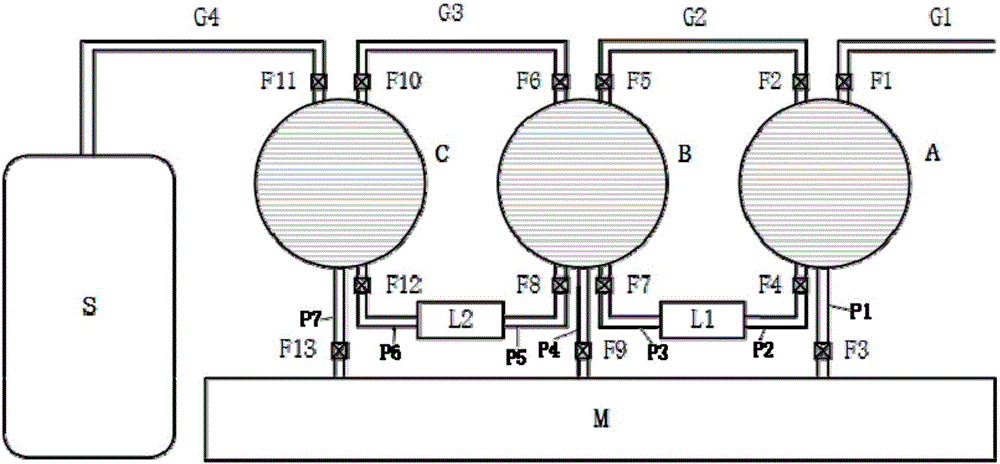
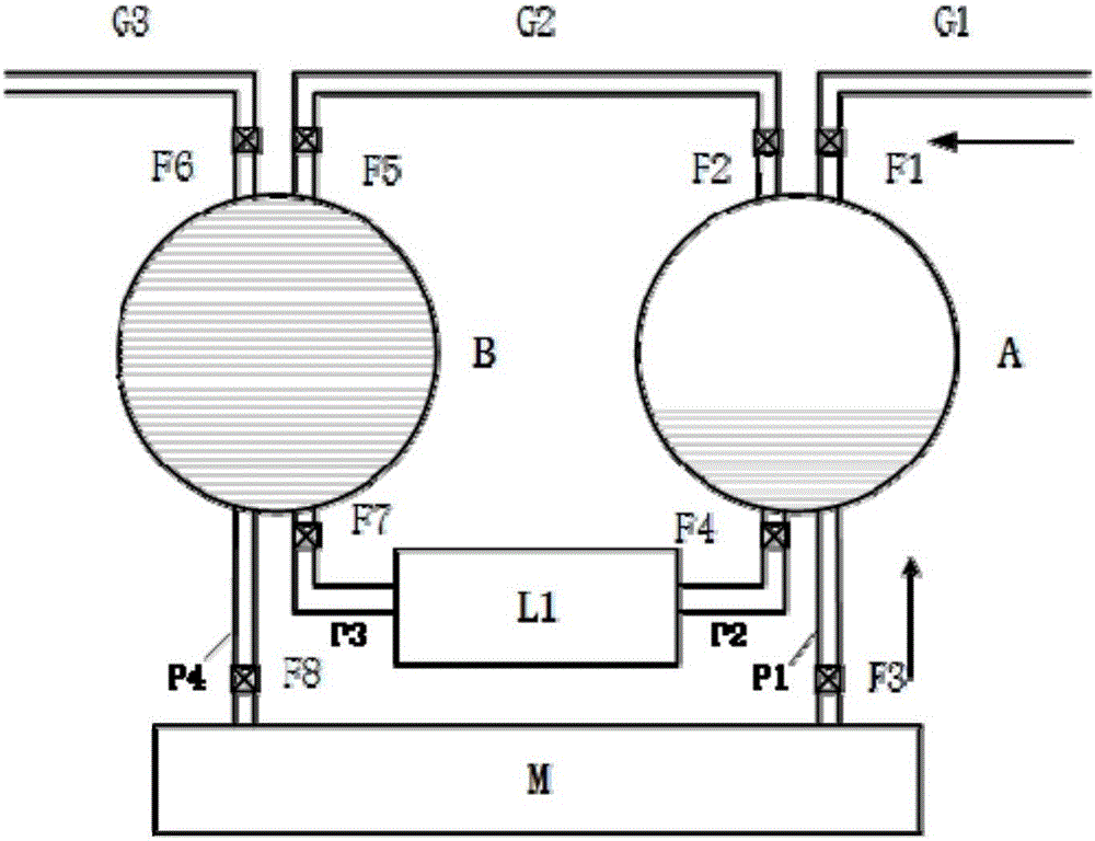
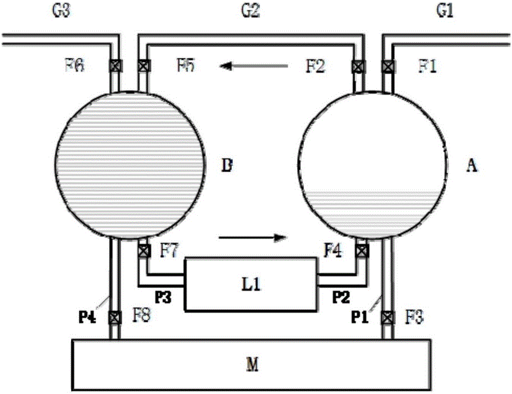
[0029] The basic structure of the compressed air energy storage system of the present invention is as follows: figure 1As shown: A, B, and C are three liquid pistons with increasing pressure levels in sequence, which are connected sequentially through gas pipelines G2 and G3. Liquid piston A with the lowest pressure level is set to connect low-pressure gas pipeline G1 to an external low-pressure gas source, and the liquid piston C is connected to the gas storage system S through the gas pipeline G4, the liquid pistons A and B, B and C are connected through the liquid driving devices L1 and L2 respectively, and A, B and C are connected to the outside through the liquid pipelines P1, P4 and P7 respectively Hydraulic equipment M. There are valves on each pipeline to control the operation of the system.

[0030] Liquid piston A is the liquid piston with the lowest pressure r...


PUM


Abstract

The invention belongs to the technical field of large-capacity electric energy storage and particularly relates to a compressed air energy storage system capable of achieving stepped gas compression and expansion through the equal-pressure migration technology. Liquid pistons are sequentially connected according to pressure-resisting level, the upper portions of every two adjacent liquid pistons are connected through a gas pipeline, and the lower portions of every two adjacent liquid pistons are connected through a liquid driving device. Each liquid piston is connected to external hydraulic equipment through a pipeline. The liquid piston with the lowest pressure-resisting level is connected with a low-pressure gas pipeline, and the liquid piston with the highest pressure-resisting level is connected with a gas storage system. According to the compressed air energy storage system, the stepped compression and expansion processes of gas in the liquid pistons are achieved, the gas is transferred between the liquid pistons with different levels through the equal-pressure migration technology, the pressure bearing change range of the liquid pistons is reduced, the equipment safety is improved, the service life of the liquid pistons is prolonged, and the manufacturing cost of equipment can be greatly reduced.

Description

technical field [0001] The invention belongs to the technical field of large-capacity electric energy storage, and in particular relates to a compressed air energy storage system that utilizes isobaric migration technology to realize gas staged compression and expansion. Background technique [0002] With the large-scale access of new energy to the grid, energy storage technology is widely used to solve the intermittency and volatility of new energy because it can provide sufficient peak-shaving capacity. Among them, compressed air energy storage technology is widely used and has great development prospects. [0003] There is already a technology that applies hydraulic turbines to compressed air energy storage, and realizes the combined power generation and energy storage of hydraulic turbines and compressed air energy storage technologies. This process uses liquid pistons to compress air with water as the medium, solving the problem of air compression. Adjustment problems,...

Claims


Application Information

Patent Timeline
Patent Type & Authority Applications(China)
IPC IPC(8): F04B41/02F04B41/06F04B39/00F04B39/10
CPCF04B39/0011F04B39/10F04B41/02F04B41/06Y02E60/16
Inventor 姜彤陈紫薇谭明甜傅昊
Owner NORTH CHINA ELECTRIC POWER UNIV (BAODING)
Learn More