
Dispensing device with piston pump

Inactive Publication Date: 2006-07-20
REXAM AIRSPRAY
View PDF17 Cites 13 Cited by
  • Summary
  • Abstract
  • Description
  • Claims
  • Application Information

AI Technical Summary

Benefits of technology

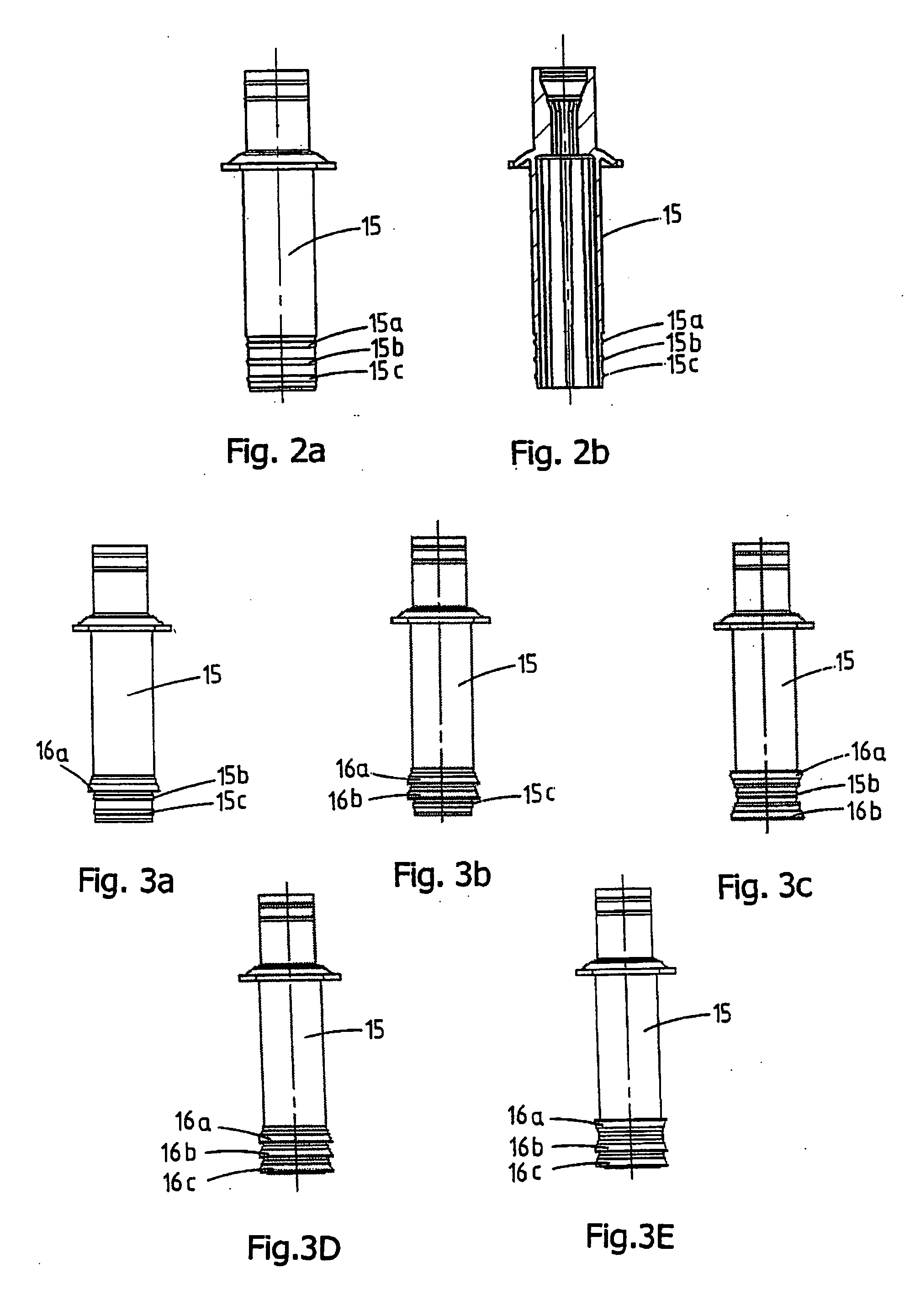
[0011] In a preferred embodiment the piston comprises three locations for fixing the one or more sealing elements. The presence of three locations generally gives sufficient freedom for fixing sealing elements for a seal suitable for the liquids commonly used.
[0012] At least one of the one or more sealing elements preferably comprises a lip which at least partially extends in a direction of movement of the piston. Such a lip has been found to be suitable for resting in a sealing manner against a wall of the pump housing, the shape also providing a scraping effect, which is particularly effective in preventing liquid residues from clinging to the wall.
[0014] It is advantageously possible to provide a piston with two sealing elements, each with a lip, one of the two lips extending in the direction of the pump stroke, in other words in the direction of the pump chamber, while the other lip extends in the opposite direction, i.e. in the direction of the return stroke, or facing away from the pump chamber.
[0015] The dispensing device according to the invention is advantageously suitable for a dispensing device for foam. Liquids which are suitable for forming a foam in a dispensing device are in fact generally thin. Such a thin liquid can relatively easily pass a seal. Placing several seals one after the other, for example three lips in a row, now gives better protection against leakage because, if the thin liquid passes the first lip, the liquid is still in a protected environment through the presence of the next lip.
[0017] Now in a foam pump air is pumped at 7 to 11 times the volume of the liquid pumped (can also sometimes be more or less than that). During the pumping process this air also moves (in a turbulent manner) past the liquid piston, and the air causes a drying-out effect on the liquid present in the air pump chamber. This means that, if there is slight leakage, the already thin liquid dries out more quickly, which can result in the liquid pump running stiffly. Such stiff running can be prevented by providing an improved seal according to the invention.
[0018] The invention further relates to a kit for producing a piston with one or more sealing elements for a dispensing device, comprising at least one piston with two or more locations for fixing the one or more sealing elements, and a number of sealing elements from which the one or more sealing elements to be fixed on the locations of the piston can be selected on the basis of a liquid to be pumped with the piston pump. With such a kit, the piston can be adapted in a simple manner during the assembly, in order to provide a suitable piston seal for the liquid to be pumped with the piston pump, by correctly selecting and placing one or more sealing elements on the piston.

Problems solved by technology

It is possible for a certain type of seal to be suitable for sealing a piston pump for a particular liquid, while the same seal is less suitable, or is even unsuitable, for another liquid.
It is remarked that in particular very thin liquids or liquids which tend to stick to or cake on the parts of the piston pump can cause problems with respect to the sealing.
A disadvantage of the known dispensing devices is that after production of the piston the seal of the liquid pump is difficult or impossible to adapt to the requirements of the liquid for which the piston pump is being used.

Method used


Image

  • Dispensing device with piston pump
  • Dispensing device with piston pump
  • Dispensing device with piston pump

Examples


Embodiment Construction

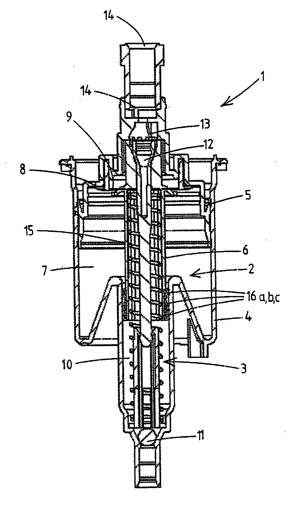
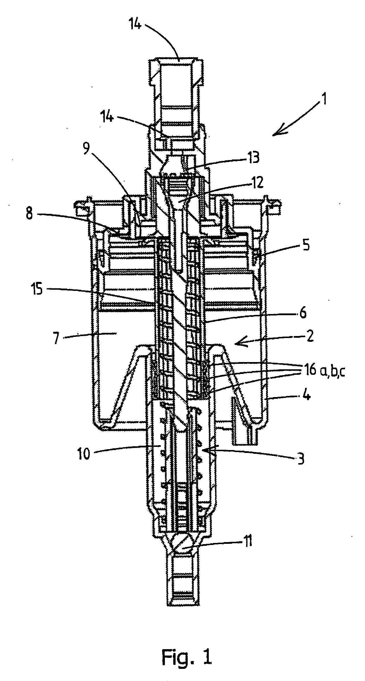
[0025]FIG. 1 shows a foam pump for dispensing a foam, which foam pump is indicated in its entirety by reference numeral 1. The foam pump 1 can be fixed by means of a fixing collar on a reservoir in which the liquid to be pumped is stored. The foam pump comprises an air pump 2 and a liquid pump 3. The pump housing of both the air pump 2 and the liquid pump 3 is formed by a double cylinder 4, in which an air piston 5 and a liquid piston 6 to be operated with a common control button (not shown) are fitted.

[0026] The air piston 5 together with a part of the double cylinder 4 and the liquid piston forms an air pump chamber 7, by means of which air can be pumped by the air piston 5 performing a telescopic movement relative to the double cylinder 4. This pumping action is made possible by the fact that the air pump 2 is provided with an inlet valve 8 and an outlet valve 9.

[0027] In a corresponding manner, the liquid piston 6 together with a part of the double cylinder 4 forms a liquid pu...


PUM


Abstract

The invention relates to a foam-dispensing device for dispensing a foam, comprising a manually operated pump assembly. The pump assembly comprises a liquid piston pump for pumping the liquid, and an air pump for pumping air, the liquid and air to be pumped being mixed together to form a foam which is dispensed through a dispensing aperture. The liquid piston pump comprises a pump housing, for example a cylinder, a liquid piston which is movable telescopically in the pump housing, and one or more sealing elements to be fixed on the liquid piston in order to seal the liquid piston in the pump housing. The liquid piston comprises at least two locations for fixing the one or more sealing elements. The invention further relates to a kit for producing a piston with one or more sealing elements for such a dispensing device, and a method for producing a piston pump for such a dispensing device.

Description

SUBJECT OF THE INVENTION [0001] The invention relates to a foam-dispensing device. The invention further relates to a dispensing device, a kit for assembling a piston for such a foam-dispensing device and a method for producing such a device. BACKGROUND OF THE INVENTION [0002] Dispensing devices are generally used for pumping a liquid out of a reservoir. More particularly, the invention relates to a manually operated dispensing device for dispensing a foam, which device is preferably held in the hand during operation. In such a foam-dispensing device, in addition to the piston pump for pumping a liquid, an air pump is provided for pumping air. The pumped air and liquid are mixed together to form a foam before dispensing. Such foam-dispensing devices are also generally known. [0003] The known piston pump is provided with a seal which contacts in a sealing manner to pump housing. In a known embodiment this seal is moulded on as part of the piston. In another known embodiment of a pist...

Claims


Application Information

Patent Timeline
IPC IPC(8): B67D5/58B67D7/76
CPCB05B11/3001B05B11/3042B05B11/3084B05B11/3087B05B7/0025B05B11/105B05B11/1087
Inventor VAN DER HEIJDEN, EDGAR IVO MARIA
Owner REXAM AIRSPRAY
Learn More