Eureka AIR delivers breakthrough ideas for toughest innovation challenges, trusted by R&D personnel around the world.

System for operating one or more suspended laser projectors to project a temporary visible image onto a surface

a laser projector and surface technology, applied in the direction of instruments, movable markers, sport apparatus, etc., can solve the problems of jarring movements, loss of possession, and relatively simple sport, and achieve the effect of preventing jarring movements

Inactive Publication Date: 2007-05-22
THOUGHT DEVMENT
View PDF17 Cites 19 Cited by
  • Summary
  • Abstract
  • Description
  • Claims
  • Application Information

AI Technical Summary

Benefits of technology

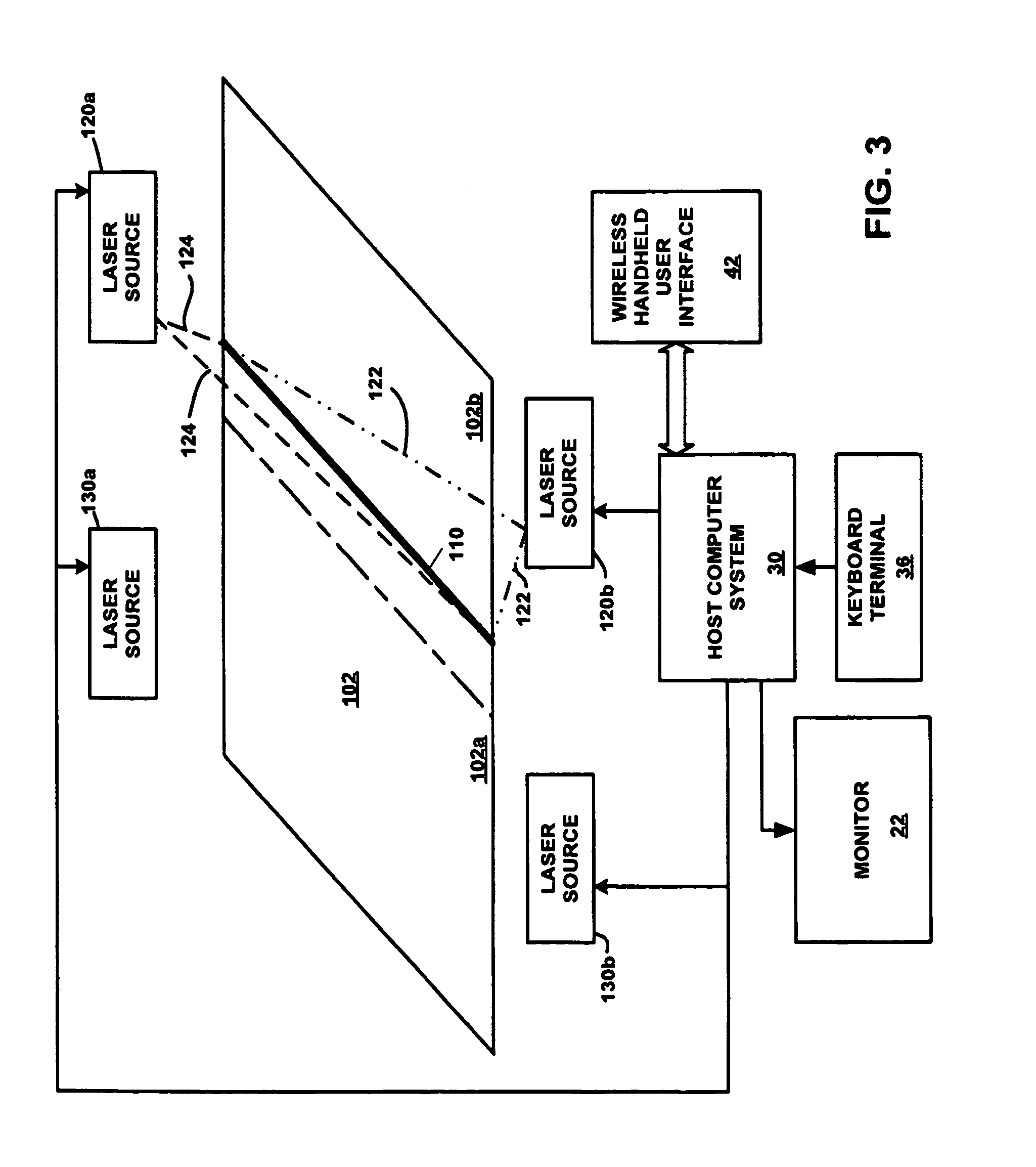
[0017]The projection module is supported at an elevated location above the target surface by a suspension system that incorporates a sensor adapted to detect the angular orientation of the projector module relative to a preferred orientation of the projection module and with respect to at least two axes of rotation. The suspension system further includes a motorized drive system adapted to make adjustments to the position of the projection module in order to maintain it in the preferred orientation. Adaptively stabilizing the angular orientation of the projection module prevents jarring movements of the image projected upon the target surface, making it suitable for use in projecting a reference line despite wind gusts, building vibrations, and the like. In accordance with an exemplary embodiment of the invention, the suspension system is further adapted to move the projection module relative to the longitudinal and transverse axes of the target surface. Thus, the projection module can be conveyed from a first, position-stabilized location from which an image can be projected upon a first region of the target surface to a second, position-stabilized location from which an image can be projected upon a second region of the target surface.
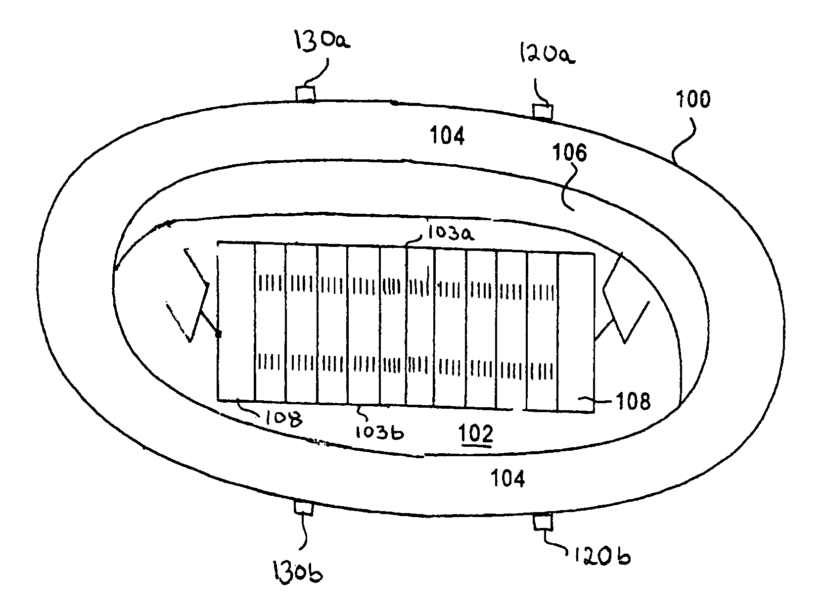
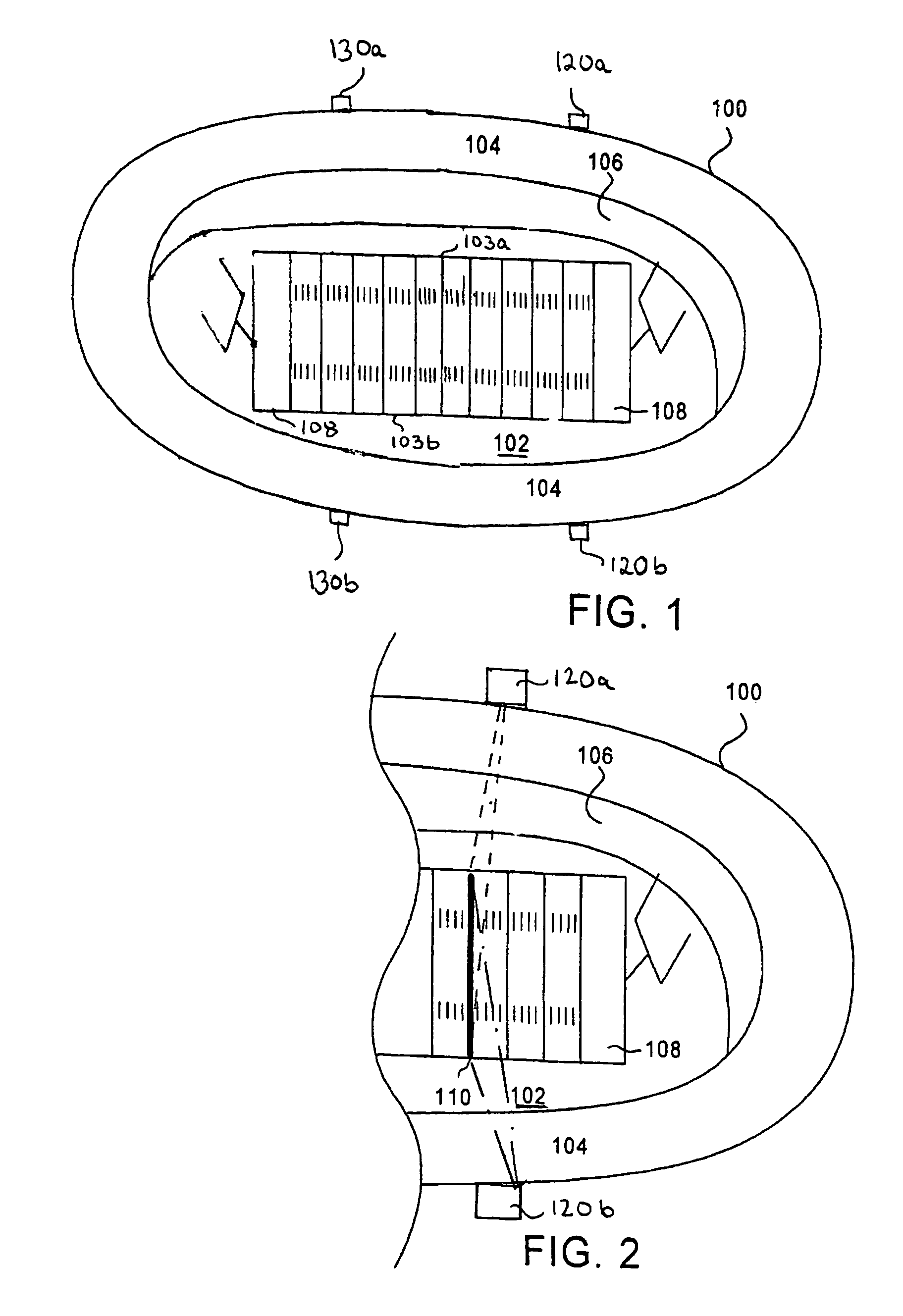
[0018]Under certain ambient lighting and other installation conditions, it is contemplated that a surface may be divided into multiple regions or zones. This allows the distance over which each beam must travel to be kept within a range that is consistent with the intensity, divergence and line width demands for proper viewing. Also, it avoids the problem of interruptions in the projected beam(s) which might be caused by a suspended camera platform or other movable or fixed structure disposed above the target surface. In that regard, and by way of illustrative example, it may be desirable to longitudinally divide a target surface such as a football field into two regions with each of two projection modules being supported by a respective suspension system and movable within a corresponding region. Indeed, providing an arrangement of plural, independently movable, suspended projection modules has a number of unique advantages. For example, in the context of a football event, it would be possible to utilize one projection module to project light within a vertical plane that extends upwardly from the line delineating the end zone while using another projection module to project light within a plane that extends upwardly from the first down line. By way of further example, the left and right boundaries of a field goal might be delineated using first and second, parallel vertical planes of light each projected by a corresponding one of the projection modules. By way of yet another example, during halftime, multiple advertisements, logos, and the like may be simultaneously directed to discrete groups of fans in the stadium depending upon their viewing angle.

Problems solved by technology

If the offense falls short, however, possession is lost and the two teams reverse their roles.
Although the game of football has become a relatively complex sport, involving literally hundreds of millions of invested dollars, this time consuming system has remained relatively the same since the conception of the sport.
A number of approaches intended to ameliorate the aforementioned deficiencies have been proposed over the years, but none of them has met with any degree of commercial success.
One of the principal drawbacks of these systems is the time-consuming and tedious method of operation.
Another drawback associated with the aforementioned systems is that the low-intensity output of these lasers is far too low to be visible by the players, let alone by an audience in, for example, a stadium setting.
As it turns out, players intent on getting the ball past the first yard line—and focused on the sideline markers long enough to be “blindsided” by the defense—have suffered very serious neck and back injuries.
Unfortunately, neither the players, game officials, nor the fans attending such games can actually see this virtual line.
It is thus reasonable to conclude that given the rapid and widespread adoption of a virtual visible line marking system—whose enjoyment is strictly limited to television viewers, it has heretofore been deemed impossible or impracticable to project a real, visible line onto the grassy surfaces which characterize most athletic fields.

Method used


Image

  • System for operating one or more suspended laser projectors to project a temporary visible image onto a surface
  • System for operating one or more suspended laser projectors to project a temporary visible image onto a surface
  • System for operating one or more suspended laser projectors to project a temporary visible image onto a surface

Examples


Embodiment Construction

[0029]In connection with the exemplary football stadium installation depicted in FIGS. 1 and 2, it will be understood that the term “target surface” refers to the surface of an athletic field that is entirely or substantially covered by real or artificial turf grass. By appropriate beam wavelength, output power level selection, and / or placement of multiple laser sources, the poor light scattering performance of such non-smooth surfaces can be overcome so that spectators can easily see the line(s) so-projected—from most, if not all, vantage points within the seating area or a stadium or arena—even in peak daylight ambient lighting conditions. It should thus be understood that although the exemplary,embodiments illustrated and described herein relate specifically to the projection of a visible straight line onto the grass surface of a football field, the teachings of the present invention are equally applicable to the projection of other types of lines—including images, logos, adverti...


PUM


Abstract

A temporary visible image, such as a first down reference line, corporate logo, or text is projected onto a target surface by an orientation-stabilized, fiber-fed laser projector. The projector may include at least one cylindrical lens or at least one pair of X-Y scanners. One or more remotely located lasers, supplying optical energy at a single wavelength to the projector, accommodate projection of a monochromatic line pattern. Multi-colored images are accommodated by supplying, to the projector, the output of a plurality of lasers operating at different wavelengths within the visible band. The projector is suspended and conveyed as a unitary assembly by a suspension system adapted to maintain the projectors angular orientation and dynamically stabilize the image. If desired, two or more independently-suspended projection modules or groups of modules adapted to move in unison or independently over the length of the field may be employed.

Description

REFERENCE TO RELATED APPLICATIONS[0001]This application is a continuation-in-part of U.S. patent application Ser. No. 10 / 838,057 filed on May 3, 2004 now U.S. Pat. No. 6,895,677 and entitled “SYSTEM FOR OPERATING ONE OR MORE LASERS TO PROJECT A VISIBLE LINE ONTO A SURFACE” which is a continuation-in-part of U.S. patent application Ser. No. 10 / 385,219 filed on Mar. 10, 2003 and entitled “SYSTEM FOR OPERATING ONE OR MORE SYNCHRONIZED LASERS TO PROJECT A VISIBLE LINE ONTO A SURFACE”, now U.S. Pat. No. 6,796,041 and of U.S. patent application Ser. No. 10 / 385,218 filed on Mar. 10, 2003 and entitled “SYSTEM AND METHOD FOR OPERATING GROUPS OF LASERS TO PROJECT A VISIBLE LINE OF DEMARCATION ONTO DISCRETE REGIONS OF AN ATHLETIC FIELD”, now U.S. Pat. No. 6,751,880, both of which being continuations-in-part of U.S. patent application Ser. No. 10 / 320,304 filed on Dec. 16, 2002 and entitled “SYSTEM AND METHOD FOR DYNAMICALLY MARKING ATHLETIC FIELDS USING A HANDHELD USER INTERFACE”.BACKGROUND OF ...

Claims


Application Information

Patent Timeline
Patent Type & Authority Patents(United States)
IPC IPC(8): G01C15/06G01C15/00
CPCG01C15/004Y10S33/21A63C2019/067A63C19/065A63C2203/12A63C2203/14A63C2203/22A63C2203/24A63C2203/18
Inventor AMRON, ALAN B.DINICOLA, BRIAN K.
Owner THOUGHT DEVMENT
Why Eureka
Eureka Blog
Learn More