
Process for twist-free steel cutting of rotational symmetrical surfaces

a technology of rotating symmetrical surfaces and cutting processes, which is applied in the direction of boring/drilling equipment, turning equipment, broaching machines, etc., can solve the problems of low cutting output capacity, and relative slow machining progress, and achieve good surface quality

Inactive Publication Date: 2007-05-15
BOEHRINGER WERKZEUGMASCHEN
View PDF20 Cites 30 Cited by
  • Summary
  • Abstract
  • Description
  • Claims
  • Application Information

AI Technical Summary

Benefits of technology

This approach significantly reduces surface irregularities, enhances cutting efficiency, and extends cutter lifespan while maintaining high surface quality and sealing effectiveness, reducing the need for supplementary processes and minimizing environmental impact.

Problems solved by technology

Since the cutting feed-motions, in particular in case of the workpieces hardened for an enhanced surface quality—are as a rule very small, this often leads to a relatively slow machining advance and a low cutting output capacity respectively.
While the relatively low cutting output capacity is an important economic drawback, the twisted surfaces are creating technical problems to the packings arranged on them, in particular whether they are shifting with respect to the surfaces, for example in case of a shaft rotating inside a fixed packing.
In particular in case of machines which for example out of hygiene or environment protection reasons have to run without leaking, this thing is a problem worthy of being considered.
Supplementary, because of these grooves or thread shaped prominences, the sealing elements arranged on the twisted surfaces will be often deteriorated in time at their lines or contact surfaces, or at least strongly abrasively stressed.
But in case that the cutter is as broad in the axial direction as the total rotation symmetrical surface to be obtained, there are arising, in particular on machining the hardened surfaces, very great transverse forces, and because of the dynamic instability there is a high vibration tendency.
These dynamic instabilities and the vibration respectively, are leading quickly to so great surface irregularities that in this case the surface is likewise too irregular for a perfect sealing.
If the individual cutters of the rotary broaching machine are orientated in parallel with respect to the rotation axis of the workpiece, there arises again here the problem of the great forces acting upon the cutters and thereby both a tendency to dynamic instability and vibration.
On the rotary broaching by means of a disk shaped cutter holder having the cutters on the circumference of the cutter holder, on the oblique arrangement of the straight cutters there supplementary arises the problem of obtaining a workpiece with a convex curved surface instead of an exactly cylindrical one.
This means that the cost price per workpiece will soar up because of an extended operating process involving the employing of supplementary machines, leading thereby to a considerable worsened economic efficiency.
Further on, according to the actual state of art, on the final machining of the workpiece, if possible, the buffing should be avoided since this is as a rule carried out as a damp procedure and thereby, because of the buffing slime, there arise supplementary environment and salubrity problems, thus worsening the economic efficiency.
A drawback of this procedure consists in having the axial length of the surfaces to be machined limited by the possible length of the small plates in the axial direction.

Method used


Image

  • Process for twist-free steel cutting of rotational symmetrical surfaces
  • Process for twist-free steel cutting of rotational symmetrical surfaces
  • Process for twist-free steel cutting of rotational symmetrical surfaces

Examples


Embodiment Construction

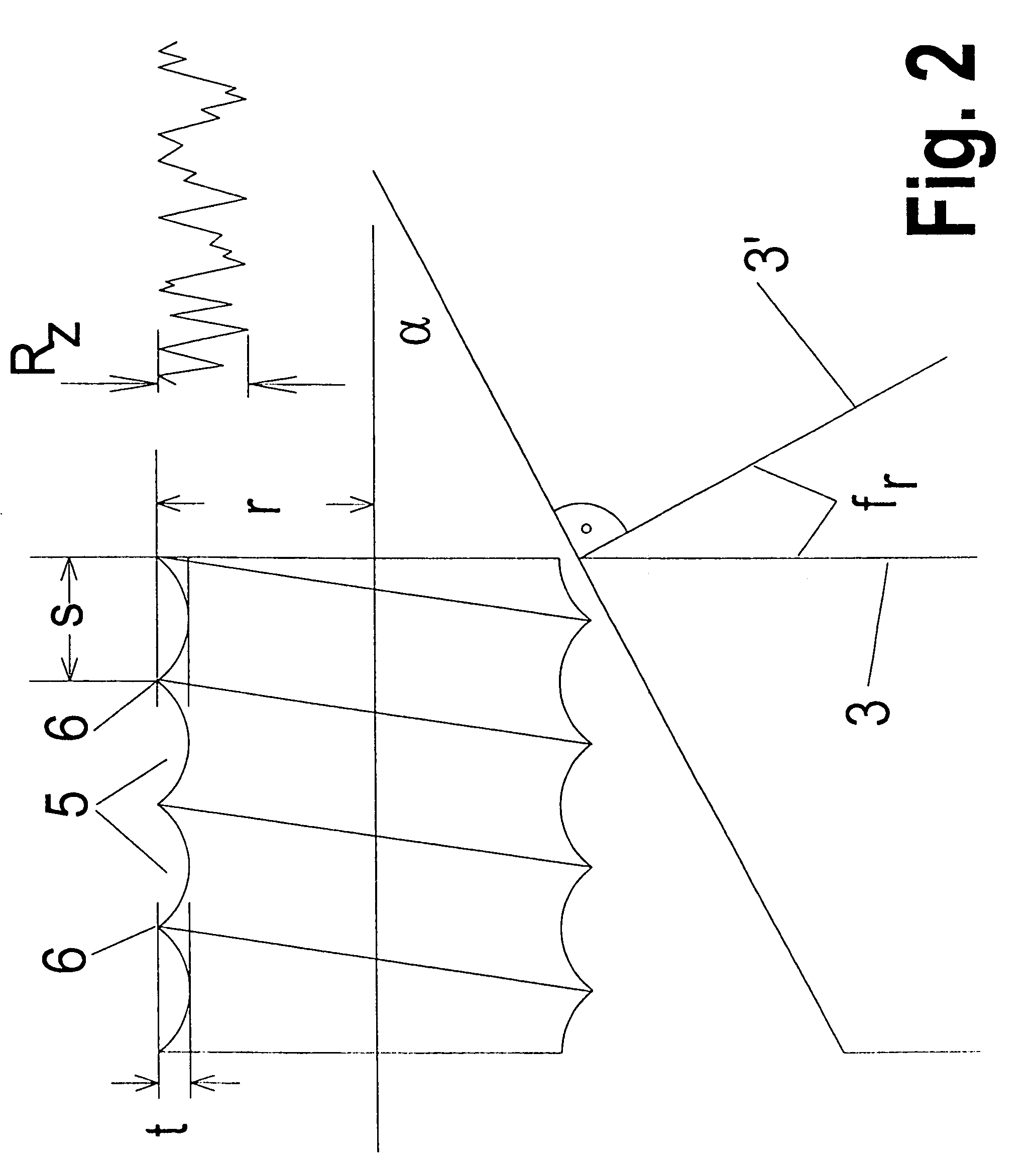
[0054]Firstly, in FIG. 3 there is represented how for example on longitudinal turning, by having the cutter shifted in the direction of the rotation axis and by its vertex radius rE, there results a thread shaped surface:

[0055]On a constant lead f, expressed in mm / workpiece rotation, there appears a helically shaped groove 5 whose pitch in the direction of the rotation axis 10 is constant at a constant lead f. The depth t′ of this groove clearly depends here on the size of the vertex radius rE of the resulting cut: the greater this vertex radius rE is, the more flattened the groove flanks are, and thereby the smaller the depth t′ will be. The dependency in accordance with the formula shows:

[0056]t=f28·rE

[0057]Only by having as a rule at least one of the cutter ridges, in particular that of the secondary cutting edge which is producing the cutting corner, positioned in an angle as small as possible, preferably in parallel to the direction of the rotation axis 10, there is usually pos...


PUM

PropertyMeasurementUnit
rotationaaaaaaaaaa
rotationaaaaaaaaaa
rotationaaaaaaaaaa

Abstract

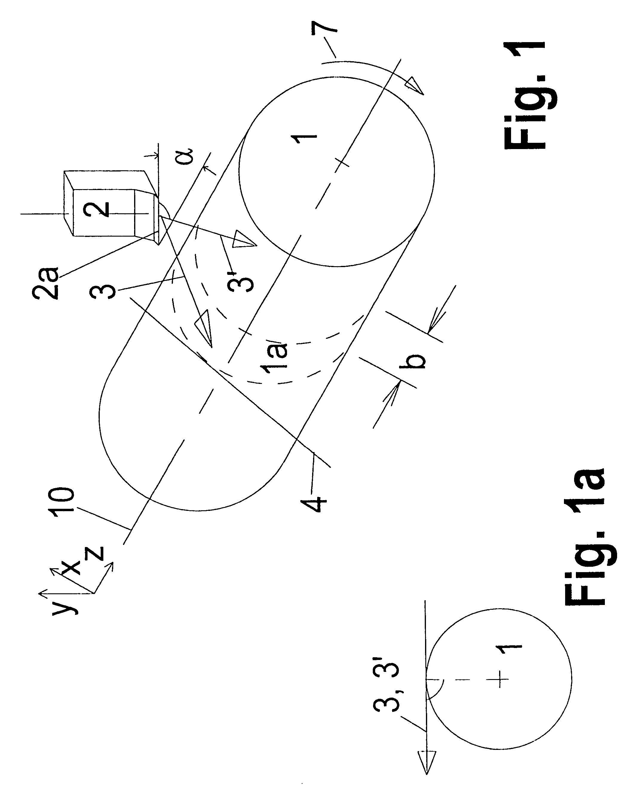
The invention relates to the cutting of rotating surfaces, especially centric symmetric surfaces (1a) of a metal workpiece (1), especially one made of steel or gray cast iron, also when said workpiece is in hardened state, by means of a geometrically determined cutter (2a) or cutters, wherein the axial extension and the material of the surface to be machined are hardly limited or not limited at all and / or the operating time during machining is reduced according to said method and / or the service life of the tool is enhanced and / or the effect of the twist-free condition is achieved, wherein at least one cutter (2a) that is skewed relative to the rotational axis (10) of the workpiece is guided during a feeding motion (3,3′) in a contacting manner on the rotating workpiece and wherein the machining parameters of the rotational axis, especially the forward feed motion in the direction of feeding and the skewed position (x) of the cutter (2a) relative to the longitudinal direction (z), are chosen in such a way that twisting in terms of the degree of twisting (s) and / or the depth of twisting (t), more particularly the depth of twisting, on the surface being machined is minimized, wherein the forward feed motion includes an axial movement.

Description

CROSS-REFERENCE TO RELATED APPLICATION[0001]This is a National Phase Application entitled “Procedure for Twist-Free Cutting Of Rotational Symmetrical Surfaces” claiming priority to PCT Application No. PCT / EP02 / 10202 filed 11 Sep. 2002, which claims priority to German Application No. 10144649.7 filed 11 Sep. 2001.FIELD OF THE INVENTION[0002]The invention concerns the steel cutting of the rotational symmetrical surfaces, in particular the central symmetrical surfaces of a rotating metallic workpiece, in particular made of steel or gray cast iron, likewise in a hardened state too, by means of a cutter or of some cutters with a certain geometry respectively.BACKGROUND OF THE INVENTION[0003]The steel cutting of the rotation symmetrical surfaces, both in a mild or hardened state, employing cutters with a certain geometry, constitutes the actual state of the art. Thereby the finishing, buffing, honing and the like procedures are partly replaced.[0004]The cutting materials to provide a long...

Claims


Application Information

Patent Timeline
Patent Type & Authority Patents(United States)
IPC IPC(8): B23B1/00B23D37/00
CPCB23B1/00B23D37/005B23B2200/369B23B2222/28Y10T407/2206Y10T82/10Y10T408/26B23B2226/125
Inventor SCHREIBER, LEORIEGEL, ADRIANKOHLHASE, MATTHIAS
Owner BOEHRINGER WERKZEUGMASCHEN
Learn More