
Method of matching a digital camera image to a database using a timestamp device

a database and timestamp technology, applied in the field of tracking and storing a digital photographic image in a database, can solve the problems of photos tending to fade, battery power and failure, and high cost of laptop computers

Inactive Publication Date: 2007-05-08
DPI +1
View PDF4 Cites 19 Cited by
  • Summary
  • Abstract
  • Description
  • Claims
  • Application Information

AI Technical Summary

Benefits of technology

[0010]The principal object of the present invention is to provide an improved method of correlating digital photographic images to a preloaded database without requiring the use of a computer.
[0012]A third object of the invention is to create an environment during the photography session that is expeditious and not disruptive to a school environment.
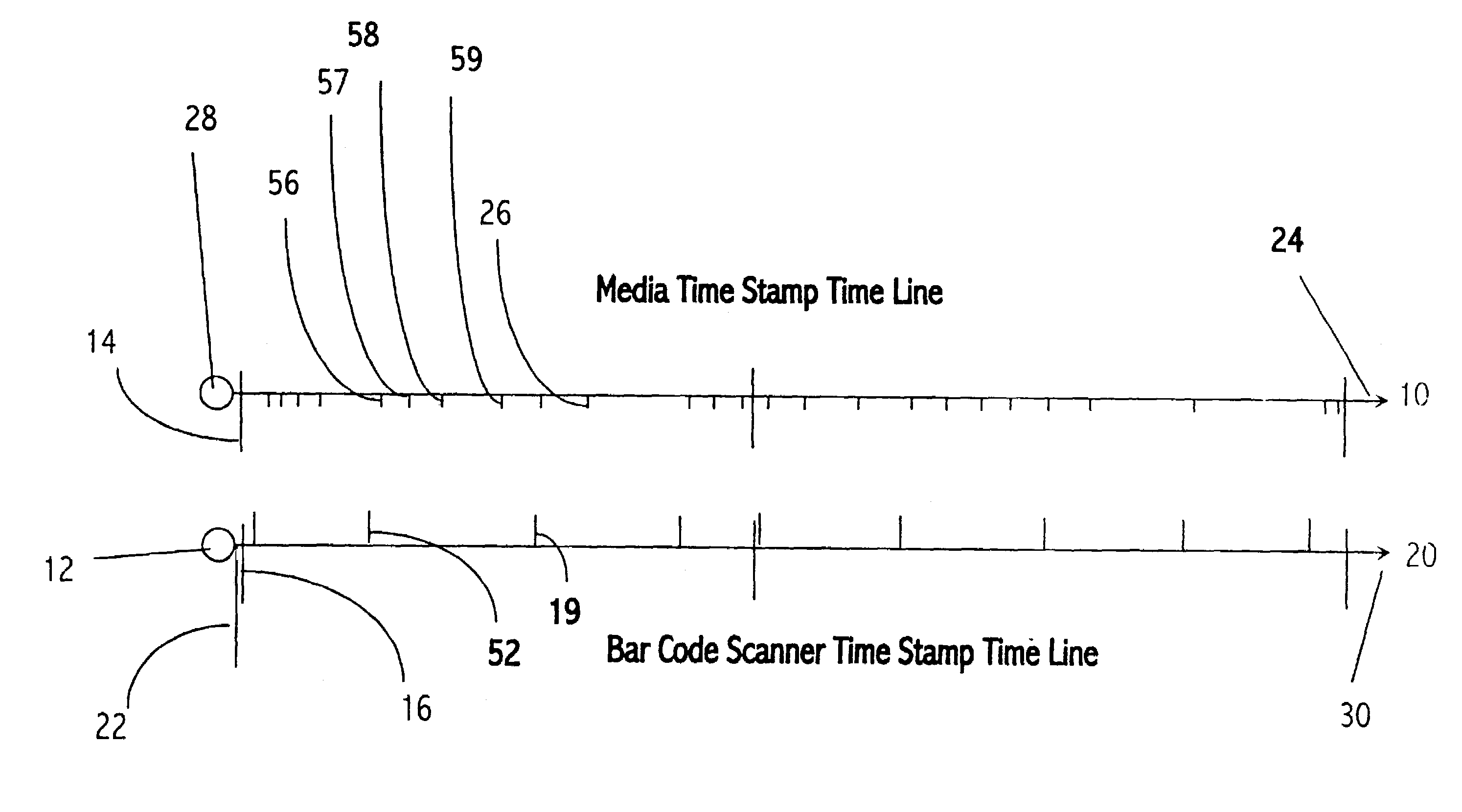
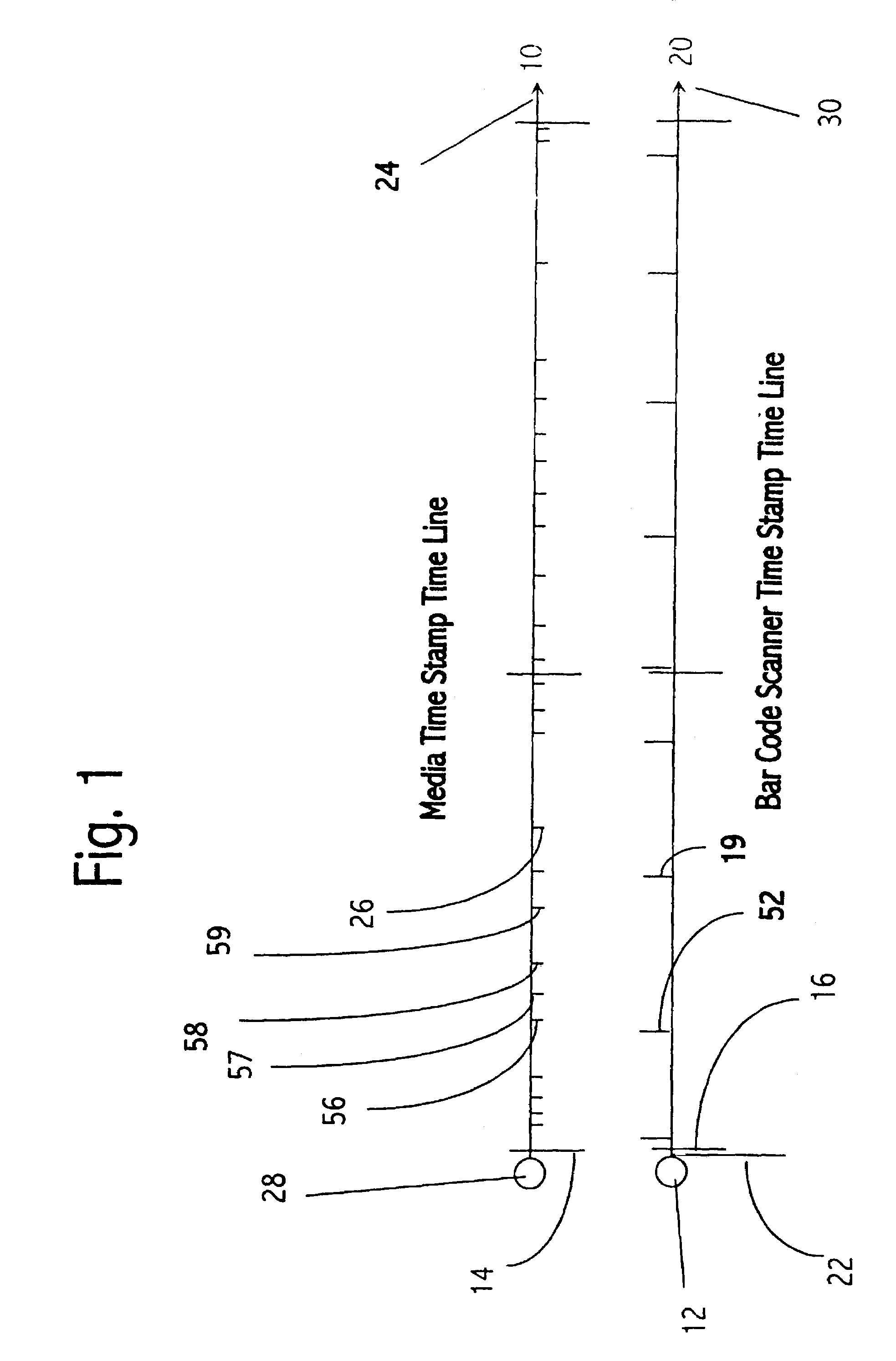
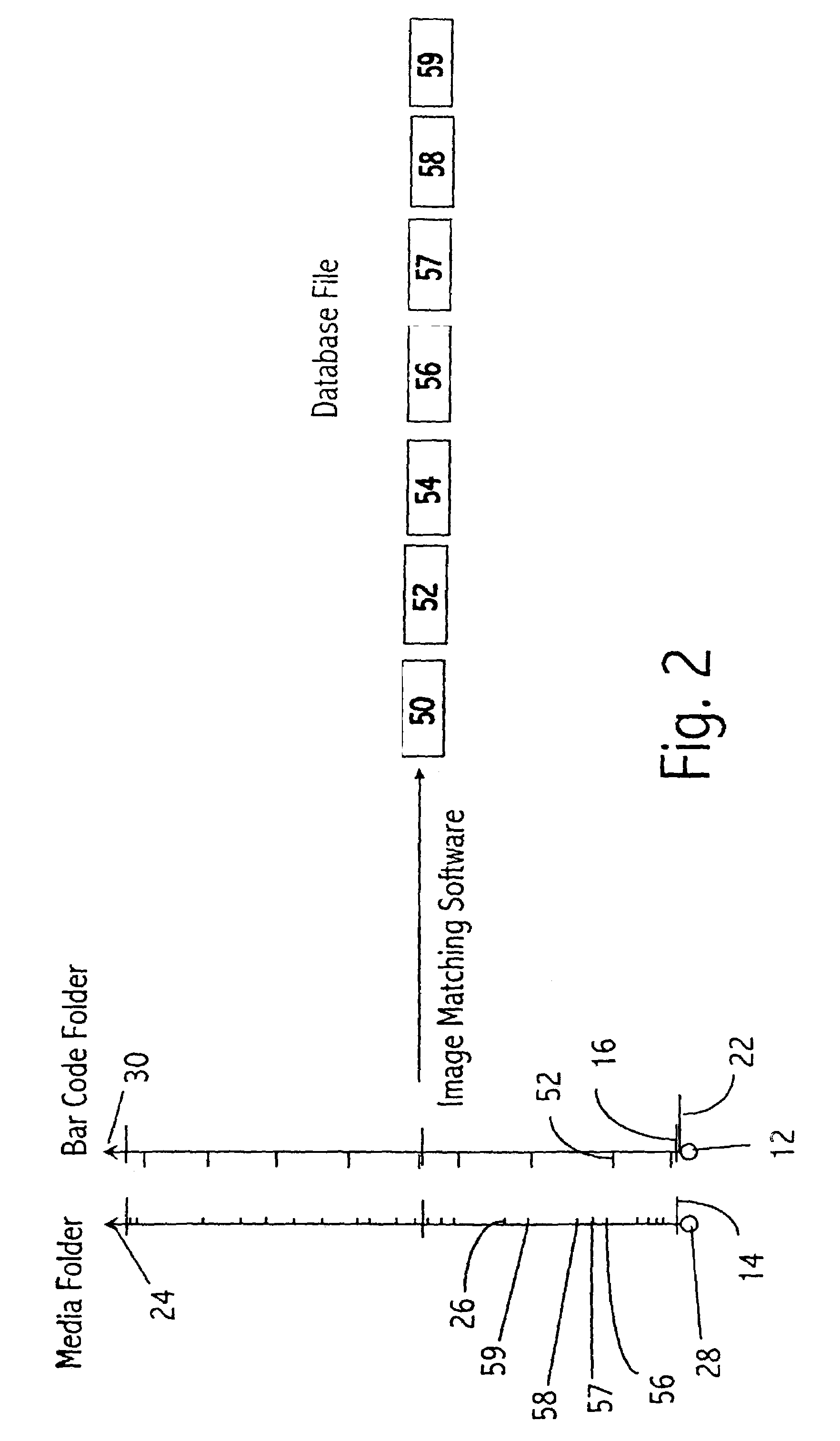
[0018]To illustrate the utility and the diversity of the method, a third example illustrates how the method can be employed to keep track of large numbers of images for subjects, as can be the case with school photographic shoots. The school provides the selected photography organization with the database of the students. The selected organization then generates an identifying bar code for each subject, where the subject is a student and the bar code is imprinted on a camera card for each student. The bar code on the camera card is a unique identifier of the student. The digital media is usually a PCMCI card, memory stick, or compact disc. The digital media stores digital images and timestamps each digital camera image at the time the picture is taken. As with the laptop system, the student having received his disbursed camera card presents the camera card to the photographer, who then wands the bar code on the camera card. The photographer takes as many photographs as required to complete the work. The digital camera is equipped with an LCD, which allows the photographer to quickly determine the quality of the photograph. However, in contrast to the laptop, the image will not be observable to the individual being photographed, unless so desired by the photographer. The next shoot begins with the presentation of the next camera card, which is swiped by the wand, records the bar code and the timestamp of the swipe. As before, the photographer takes as many pictures as required to complete the photography session for the subject. The process continues until the photography session is completed. Each of the photos will be associated with just one camera card.
[0019]The method can be slightly modified to create additional tracking and control elements. In setting up for the photography shoot, the photographer can assign / create a bar code for the digital media and for the digital camera. At the beginning of the shoot the photographer wands the digital camera bar code and wands the digital memory media. The digital memory media is quickly loaded into the camera and a time synchronizing picture is taken, which establishes the beginning time of the shoot. The process continues as previously described until the digital memory medium is filled. At this point, the next digital memory card, having its own unique bar code, is wanded and loaded into the camera. The process continues until the photography session is completed. The photographer now has a record of not only which images were shot, but also with what camera and which memory media, so that if a problem develops, the photographer can easily identify the source of the problem.

Problems solved by technology

There are some serious negatives to this process, and many of these negatives are a consequence of the fact that a laptop computer is required for each camera.
Laptop computers are expensive.
Like the camera, they are battery powered and subject to failure.
On a practical level, in judging the amount of disruption caused by the photographic session, the fact that the student can view the photos tends to slow the entire process.
Boyne does not teach the utility of a method, wherein the camera is not tethered to a computer.

Method used


Image

  • Method of matching a digital camera image to a database using a timestamp device
  • Method of matching a digital camera image to a database using a timestamp device
  • Method of matching a digital camera image to a database using a timestamp device

Examples


Embodiment Construction

[0024]A method of generating and matching digital photographic image data generated by a digital camera to a file loaded in a database, where the file has a unique identifier (UID) for a subject, said method comprising: a) providing a digital camera that records an image timestamp with every digital photographic image with a camera bar code, at least one digital memory medium with a media bar code, and a unique camera card with a card bar code for each subject; b) providing a portable bar code scanner that records the bar code and a scanner timestamp with each scan; c) scanning the camera bar code, therein recording the camera bar code and the camera timestamp; d) scanning the media bar code, therein recording the media bar code and a media timestamp; e) taking a time synchronizing picture; f) scanning the card bar code, therein recording the card bar code and a card timestamp; g) shooting the digital photographic image that is to be assigned to the subject; h) repeating step g unti...


PUM


Abstract

The invention is a method for correlating and assigning digital camera images to a database file. The method enables a photographer to keep track of large numbers of subjects and items. The method uses a timestamp from a bar code reader to synchronize recorded swipes of bar codes with the digital images created produced by the camera. The bar code reader is used to swipe identifying bar code on items or subjects that are to be tracked, such as on a student's camera card, a police investigation report or a catalogue item. The time and the bar code serve as a means to cross-reference any item or subject to the digital images. The photographs and bar code scans are downloaded into a computer, and then by inspection of the recorded times of when the scans were made and the pictures were taken, the images can be assigned to the appropriate file. The images can then be loaded into the item's or subject's file, secure in the knowledge that the images are appropriately assigned.

Description

CROSS REFERENCE TO RELATED APPLICATIONS[0001]The application claims the benefit of U.S. Provisional Application No. 60 / 358,613, filed on Feb. 21, 2002.FIELD OF THE INVENTION[0002]The invention relates to general digital photography and more particularly to a method for tracking and storing a digital photographic image in a database.BACKGROUND OF THE INVENTION[0003]Schools and other governmental organizations commonly employ digital photography to generate photo IDs. Photo IDs are used by the school to identify which students should be on the school premises, to help the students with their socialization and adaptation to the school, to aid in name recognition, and to facilitate a variety of administrative functions. In another application, the highway department uses IDs to identify drivers who are approved licensed drivers of a vehicle. Another example of photo ID use is in companies, particularly large companies and governmental agencies, to enhance security, wherein access to the...

Claims


Application Information

Patent Timeline
Patent Type & Authority Patents(United States)
IPC IPC(8): G06K9/54G06K9/60
CPCG06F17/30244H04N1/00334H04N1/32101G07C9/00031H04N1/00326H04N2201/0084H04N2201/3215H04N2201/3274G06F16/50G07C9/22
Inventor TEPERA, ED J.GATTI, BENJAMIN L.
Owner DPI
Learn More