Method and apparatus for a downhole fluorescence spectrometer

a fluorescence spectrometer and fluorescence spectrometer technology, applied in the direction of fluorescence/phosphorescence, borehole/well accessories, optical radiation measurement, etc., can solve the problems of difficult identification of hydrocarbon-bearing formations, inability to determine, and relatively expensive cores, so as to increase the intensity of illuminating ultraviolet light and increase the intensity

Inactive Publication Date: 2007-05-08
BAKER HUGHES HLDG LLC
View PDF28 Cites 14 Cited by
  • Summary
  • Abstract
  • Description
  • Claims
  • Application Information

AI Technical Summary

Benefits of technology

[0011]A reflective surface is provided behind the UV bulbs to increase the intensity of the illuminating UV light on the sample. The optically clear UV coupler or sapphire light pipe further increases the intensity. Since the intensity of the UV bulbs is temperature-dependent, the present invention monitors this light intensity. The intensity of a red line of proportional intensity in the emission spectrum of the UV bulb is monitored using light sensing devices that are already present and in use in the Baker Atlas SampleViewSM RCI tool. The strike voltage of the UV bulb also increases with temperature. The present invention counters this voltage creep providing an alternation of polarity between each strike.

Problems solved by technology

Cores are relatively expensive to obtain and must be returned to the surface for analysis.
Cuttings are obtained continuously in drilling, but have the disadvantage that it is not possible to determine at the surface exactly where the cuttings originate downhole, making the identification of hydrocarbon-bearing formations difficult.
Also, cuttings give no accurate indication of the extent of any hydrocarbon bearing formations.
A down hole environment is a difficult one in which to operate a sensor.

Method used


Image

  • Method and apparatus for a downhole fluorescence spectrometer
  • Method and apparatus for a downhole fluorescence spectrometer
  • Method and apparatus for a downhole fluorescence spectrometer

Examples


Embodiment Construction

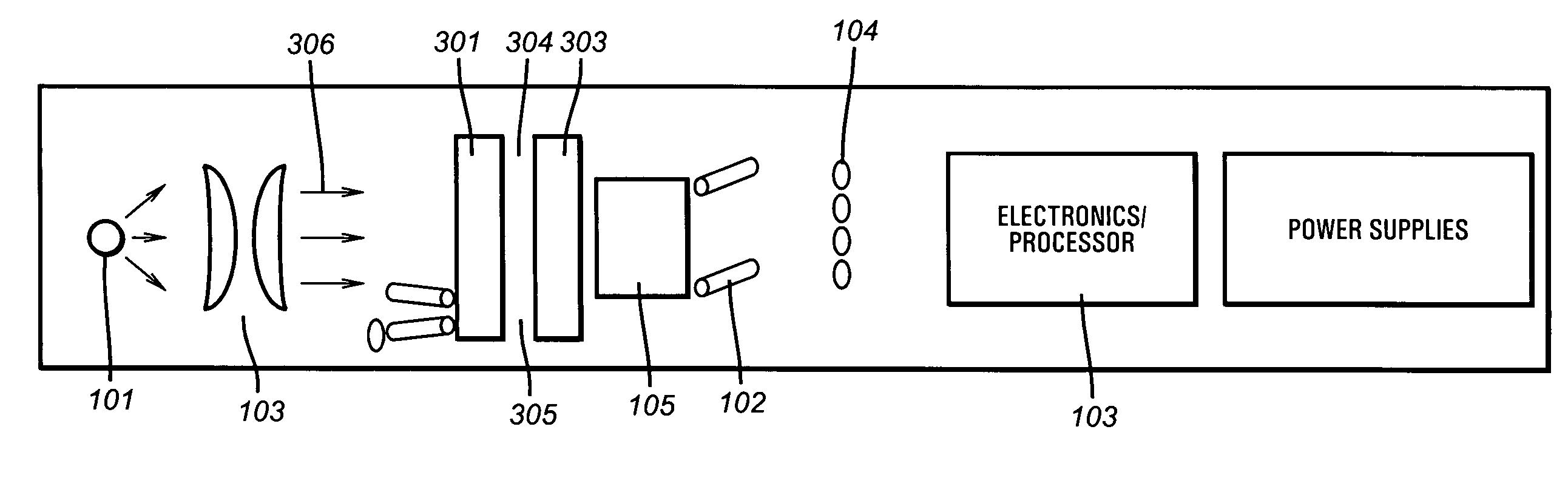
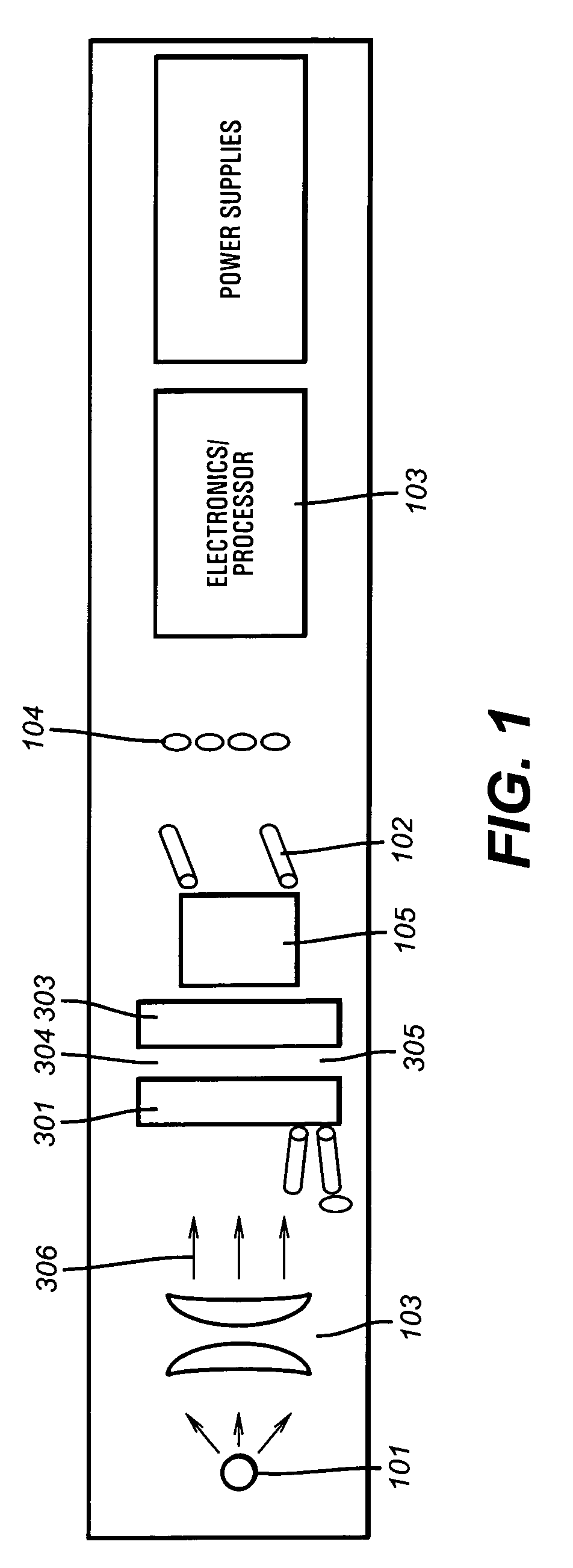
[0015]FIG. 1 illustrates the existing space layout within a downhole fluid characterization module, as, for example, the Baker Atlas SampleViewSM RCI tool. A UV light source 101 (e.g. tungsten light bulb) emits light toward a sample, and a collimating lens device 103 is positioned between the UV light source 102 and the sample collimates this light. The collimated light is incident generally perpendicular to a first sapphire window 301. Sapphire windows 301 and 303 lie generally perpendicular to the collimated beam of light 306 and are separated by a gap or channel 304 enabling a fluid sample 305 to flow between them. Reflected and fluoresced light can be used to determine sample properties. The existing down hole tools (FIG. 1) are fitted with a UV light source, which can be turned on when the tungsten light source 101 is turned off. A spectrometer 104, comprising single wavelength filters over photodiodes, enables collecting the crude oil fluorescence. Electronics / processor 308 ac...


PUM

PropertyMeasurementUnit
voltageaaaaaaaaaa
voltageaaaaaaaaaa
voltageaaaaaaaaaa

Abstract

The invention comprises an apparatus and method for simple fluorescence spectrometry in a down hole environment. The apparatus and method utilization of two UV light bulbs and an optically clear UV coupler and a fluid containment system. The optically clear UV coupler and fluid containment system are made of sapphire. The apparatus is attached in a manner that enables light transmitted from a light source on the far side of the fluid containment system to pass through a pathway in a plate holding the UV bulbs. UV light illuminates the fluid, which in turn fluoresces light. The fluoresced light is transmitted back towards the UV bulb mount and through the pathway towards an optical spectrum analyzer.

Description

CROSS-REFERENCE TO RELATED APPLICATIONS[0001]This patent application takes priority from U.S. Provisional Patent Application Ser. No. 60 / 385,633 filed on Jun. 4, 2002 entitled “A Method and Apparatus for a Downhole Fluorescence Spectrometer” by DiFoggio et al. This application is related to U.S. Pat. No. 6,798,518, issued on Sep. 28, 2004, entitled “A Method and Apparatus for a High Resolution Downhole Spectrometer” by Rocco DiFoggio, Paul Bergen and Arnold Walkow, which is hereby incorporated herein by reference in its entirety. This application is related to U.S. Pat. No. 6,683,681, issued on Jan. 27, 2004, entitled “A Method and Apparatus for a Derivative Spectrometer” by Rocco DiFoggio, Paul Bergen and Arnold Walkow, which is hereby incorporated herein by reference in its entirety. This application is related to the U.S. patent application Ser. No. 10 / 119,492 filed on Apr. 10, 2002 by Rocco DiFoggio et al., entitled “A Method and Apparatus for Downhole Refractometer And Attenuat...

Claims


Application Information

Patent Timeline
Patent Type & Authority Patents(United States)
IPC IPC(8): G01N21/64G01V5/08G01V1/00E21B49/08G01J3/06G01J3/26G01J3/433G01J3/44G01N21/03G01N21/35G01N21/85
CPCE21B49/08G01J3/06G01J3/26G01J3/433G01J3/4406G01N21/359G01N21/64E21B2049/085G01J3/0202G01J3/0262G01N21/0317G01N2021/6421G01N2021/6439G01N2021/6482G01N2021/855G01N21/3577E21B49/0875
Inventor DIFOGGIO, ROCCOWALKOW, ARNOLDBERGREN, PAUL
Owner BAKER HUGHES HLDG LLC
Why Eureka
Try Eureka