Motor-driven type power steering apparatus

Active Publication Date: 2007-05-08
JTEKT CORP
View PDF10 Cites 19 Cited by
  • Summary
  • Abstract
  • Description
  • Claims
  • Application Information

AI Technical Summary

Benefits of technology

[0007]This invention has been made in view of the above circumstances, and a main object of the invention is to provide a motor-driven type power steering apparatus in which a drive gear can be moved in directions to increase and decrease the rotation-axis distance, and besides a structure around the drive gear can be made compact.

Problems solved by technology

However, much time is required for this assembling operation.
However, in the related motor-driven type power steering apparatus of the above construction in which the amount of backlash is reduced by the use of the rubber ring, each time the steering operation is effected, a load and a rotational torque are applied to the rubber ring in a radial direction, and therefore the rubber ring is liable to be subjected to deterioration such as permanent set in fatigue.

Method used


Image

  • Motor-driven type power steering apparatus
  • Motor-driven type power steering apparatus
  • Motor-driven type power steering apparatus

Examples


embodiment 1

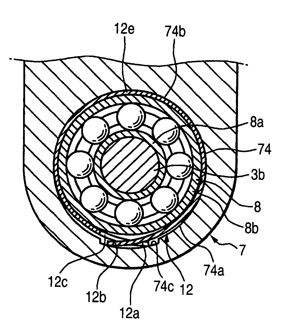
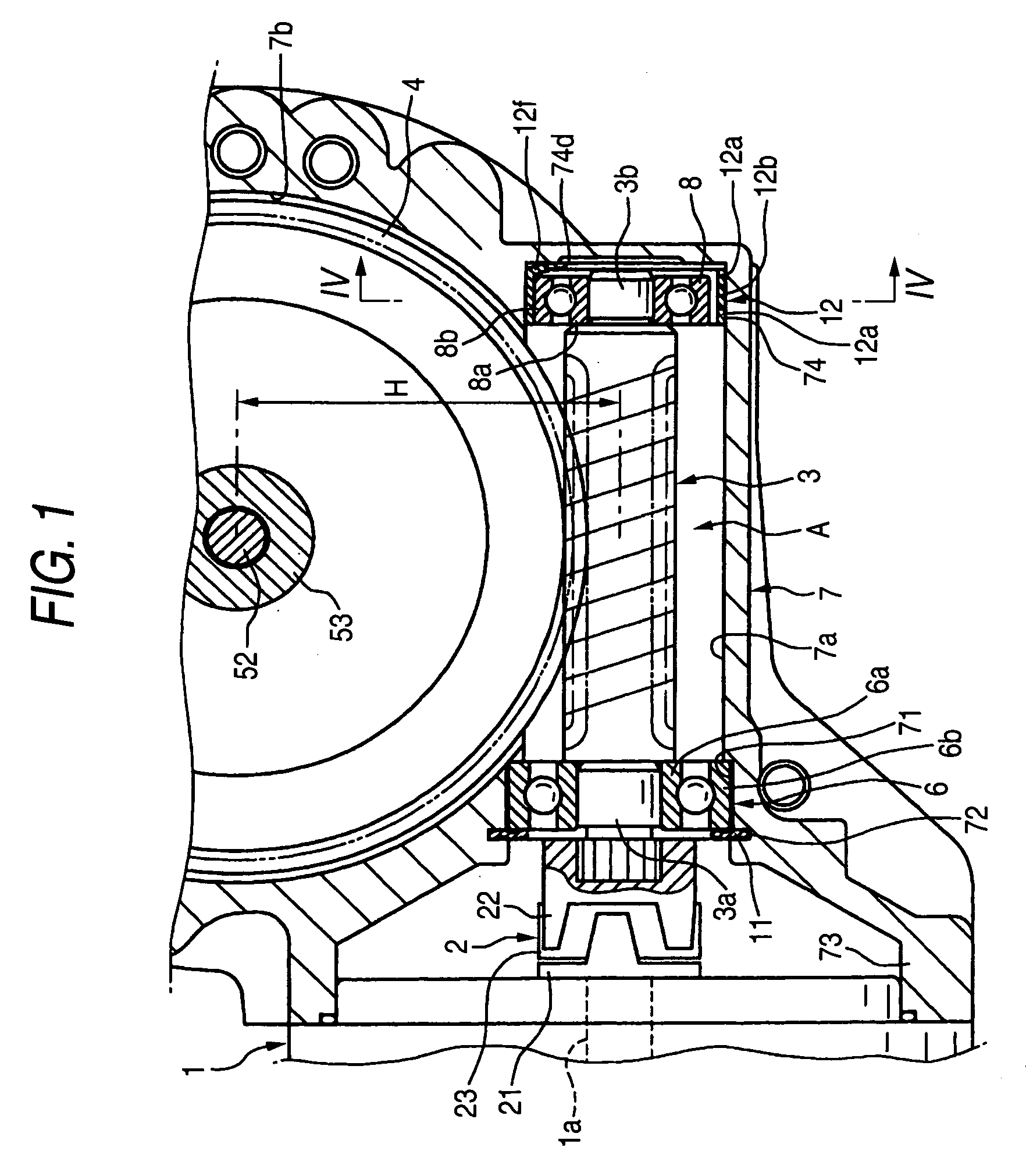
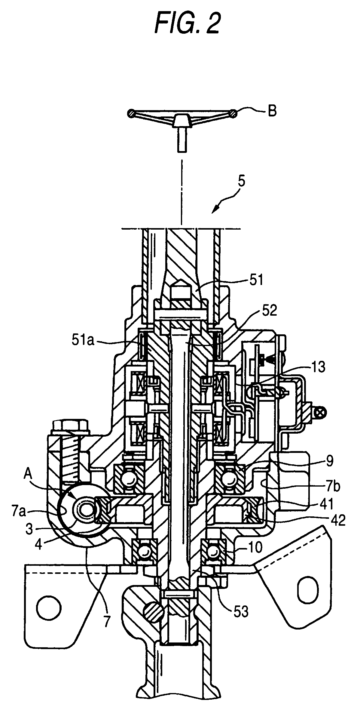
[0028]FIG. 1 is an enlarged cross-sectional view showing the construction of a reduction gear mechanism of a motor-driven type power steering apparatus of the invention, and FIG. 2 is a cross-sectional view showing the overall construction of the motor-driven type power steering apparatus.

[0029]The motor-driven type power steering apparatus comprises a motor 1 for steering-assisting purposes, the reduction gear mechanism A, and a steering unit 5 connected to the reduction gear mechanism A. The reduction gear mechanism A includes a worm 3 serving as a drive gear, which is coupled to an output shaft 1a of the motor 1 through a shaft coupling 2, and a worm wheel 4 serving as a driven gear which meshes with the worm 3.

[0030]The steering unit 5 includes: a first steering shaft 51 which is connected at one end thereof to a steering wheel B for steering purposes and has a tubular portion 51a at the other end thereof; a torsion bar 52 which is received in the tubular portion 51a of the firs...

second embodiment

[0053]FIG. 6 is a cross-sectional view showing a major portion of a second embodiment of a motor-driven type power steering apparatus of the invention.

[0054]In the motor-driven type power steering apparatus of the second embodiment, a curved leaf spring 12, generally similar to the curved leaf spring 12 of the first embodiment, has abutment portions 12g and 12g for abutting against an outer peripheral surface of a second rolling bearing 8, which is formed adjacent respectively to end portions 12a and 12b thereof, and bent portions 12h and 12h project outwardly from the abutment portions 12g and 12g, respectively. Each of the end portions 12a and 12b can be resiliently deformed to be turned about the corresponding abutment portion 12g.

[0055]In the second embodiment, the bent portions 12h and 12h are located such that a peripheral length between the two bent portions 12h and 12h is smaller than the peripheral length of the second rolling bearing 8. When the end portions 12a and 12b a...


PUM


Abstract

A motor-driven type power steering apparatus includes: a drive gear connected to an output shaft of a motor; a driven gear in mesh with the drive gear, which is connected to a steering unit; a bearing for supporting one end of the drive gear; a support portion in which the bearing is disposed; and a curved leaf spring which has a length larger than a peripheral length of the bearing and fitted between the bearing and the support portion in a resiliently deformed state. The curved leaf spring urges the bearing so that a distance between an axis of the driven gear and an axis of the drive gear decreases.

Description

BACKGROUND OF THE INVENTION[0001]The invention relates to a motor-driven type power steering apparatus using a motor as a source of generation of steering-assisting power.[0002]A motor-driven type power steering apparatus for a vehicle includes a motor for steering-assisting purposes, and a reduction gear mechanism for transmitting a rotational force of the motor to a steering unit. The power steering apparatus assists the operation of the steering unit corresponding to the rotation of the steering unit by the rotation of the motor so that the driver's labor, required for the steering operation, can be reduced.[0003]The reduction gear mechanism includes a worm serving as a drive gear which rotates in accordance with the rotation of the motor, and a worm wheel serving as a driven gear which meshes with the worm.[0004]In the motor-driven type power steering apparatus using such a reduction gear mechanism, in order to reduce the amount of backlash in meshed portions of the worm and wor...

Claims


Application Information

Patent Timeline
IPC IPC(8): B62D5/04F16C25/08F16C27/04F16C35/077F16H1/16F16H55/24F16H57/037F16H57/038F16H57/039F16H57/12
CPCB62D5/0409F16C25/08F16H55/24F16C35/077Y10T74/19623F16C27/04F16C2326/24F16C2361/61B62D5/04
Inventor NAKAMURA, YASUHIROSUGIURA, TOMONORIIWASA, SOUICHIMACHIDA, TOMOMASA
Owner JTEKT CORP
Why Eureka
Try Eureka