
Perforating gun quick connection system

a perforating gun and quick connection technology, applied in the direction of couplings, mechanical devices, borehole/well accessories, etc., can solve the problems of reducing reliability, adding additional components, and reducing the time and expense required to assemble/reassemble perforating guns, so as to achieve the effect of reducing the time and expense of assembling/reassembling perforating guns and fast and simple methods of connecting

Inactive Publication Date: 2007-05-01
BAKER HUGHES HLDG LLC
View PDF13 Cites 31 Cited by
  • Summary
  • Abstract
  • Description
  • Claims
  • Application Information

AI Technical Summary

Benefits of technology

[0015]One of the many features of the present invention involves providing a fast and simple method of connecting perforating guns. The present invention also provides for perforating guns to be assembled at field locations and allows for random length of gun hardware. Further, the time and expense required to assemble / reassemble perforating guns is reduced by utilization of the present invention.

Problems solved by technology

Transportation to and from the field to a central processing facility can be financially expensive as well as costly from a lost time standpoint.
However each of these suffer from the drawbacks that they are complex and the connection mechanisms disclosed therein contain multiple moving parts.
Additional components add complexity, which reduces reliability and adds capital and maintenance costs.
Further, none of the above noted references appears to have the capability of being refurbished or modified in the field, which limits their application to single uses and reduces their flexibility of use.

Method used


Image

  • Perforating gun quick connection system
  • Perforating gun quick connection system
  • Perforating gun quick connection system

Examples


Embodiment Construction

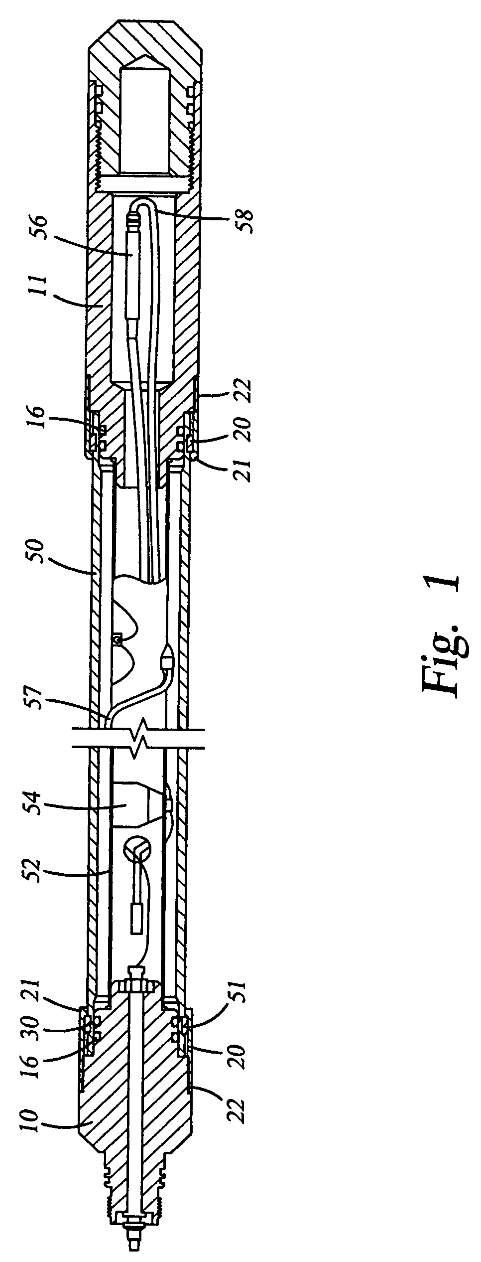
[0024]With reference to the drawings herein, a perforating gun quick disconnect system according to one embodiment of the present invention is illustrated in FIG. 1. For purposes of reference, bottom or lower refers to portions of the perforating gun located closer to the bottom of the wellbore, whereas top or higher refers to portions of the perforating gun situated closer to the wellbore opening. In one embodiment of the invention as shown in FIG. 1, a top sub 10 is secured to the upper end of a gun body 50. Seals 16 are provided on the outer radius of the top sub 10 and contact the inner radius of the upper section of the gun body 50.

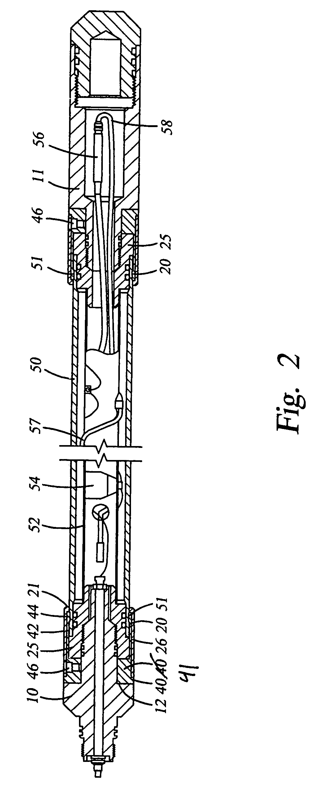
[0025]In the embodiments illustrated in FIGS. 1 and 2, the top sub 10 is substantially cylindrical with a varying diameter, and preferably with its diameter being largest at its mid-section. With regard to the embodiment of FIG. 2, it is preferred that the diameter of the top sub 10 be substantially equal to the collet base 41. Just below the top sub...


PUM


Abstract

A connection system to be used in conjunction with a perforating gun comprising a top sub formed to receive one end of a gun body of a perforating gun, a circumferential groove disposed on the outer surface of the gun body, and a collet secured to the top sub. The collet has at least one finger that engages the groove. Engaging the groove with the at least one finger of the collect connects the gun body to the top sub. A cover sleeve is included that retains the finger in connective engagement with the groove.

Description

RELATED APPLICATIONS[0001]This application claims priority from co-pending U.S. Provisional Application No. 60 / 424,486, filed Nov. 7th, 2002, the full disclosure of which is hereby incorporated by reference herein.BACKGROUND OF THE INVENTION[0002]1. Field of the Invention[0003]The invention relates generally to the field of oil and gas well services. More specifically the present invention relates to a connector assembly for a perforating gun that is quick, reliable, and simple to use.[0004]2. Description of Related Art[0005]Perforating guns containing shaped charges are used for the purpose, among others, of making hydraulic communication passages, called perforations, in wellbores drilled through earth formations. These perforations hydraulically connect predetermined zones of the earth formations to the wellbore. Perforations are needed because wellbores are typically completed by coaxially inserting a pipe or casing into the wellbore where the casing is retained in the wellbore ...

Claims


Application Information

Patent Timeline
Patent Type & Authority Patents(United States)
IPC IPC(8): E21B43/119E21B17/046F16L37/098
CPCE21B17/046F16L37/0985E21B43/119Y10T403/1641
Inventor SLOAN, MARK L.SCHUTTE, RANDY C.
Owner BAKER HUGHES HLDG LLC
Learn More