
Autonomous weapon system

a weapon system and automatic technology, applied in the field of automatic direct fire weapon systems, can solve the problems of manual weapon pointing, poor accuracy, and substantial degrading of overall combat effectiveness, and achieve the effects of reducing reaction times, enhancing effectiveness, and sufficient processing power

Inactive Publication Date: 2007-05-01
ELECTRO OPTIC SYST
View PDF42 Cites 91 Cited by
  • Summary
  • Abstract
  • Description
  • Claims
  • Application Information

AI Technical Summary

Benefits of technology

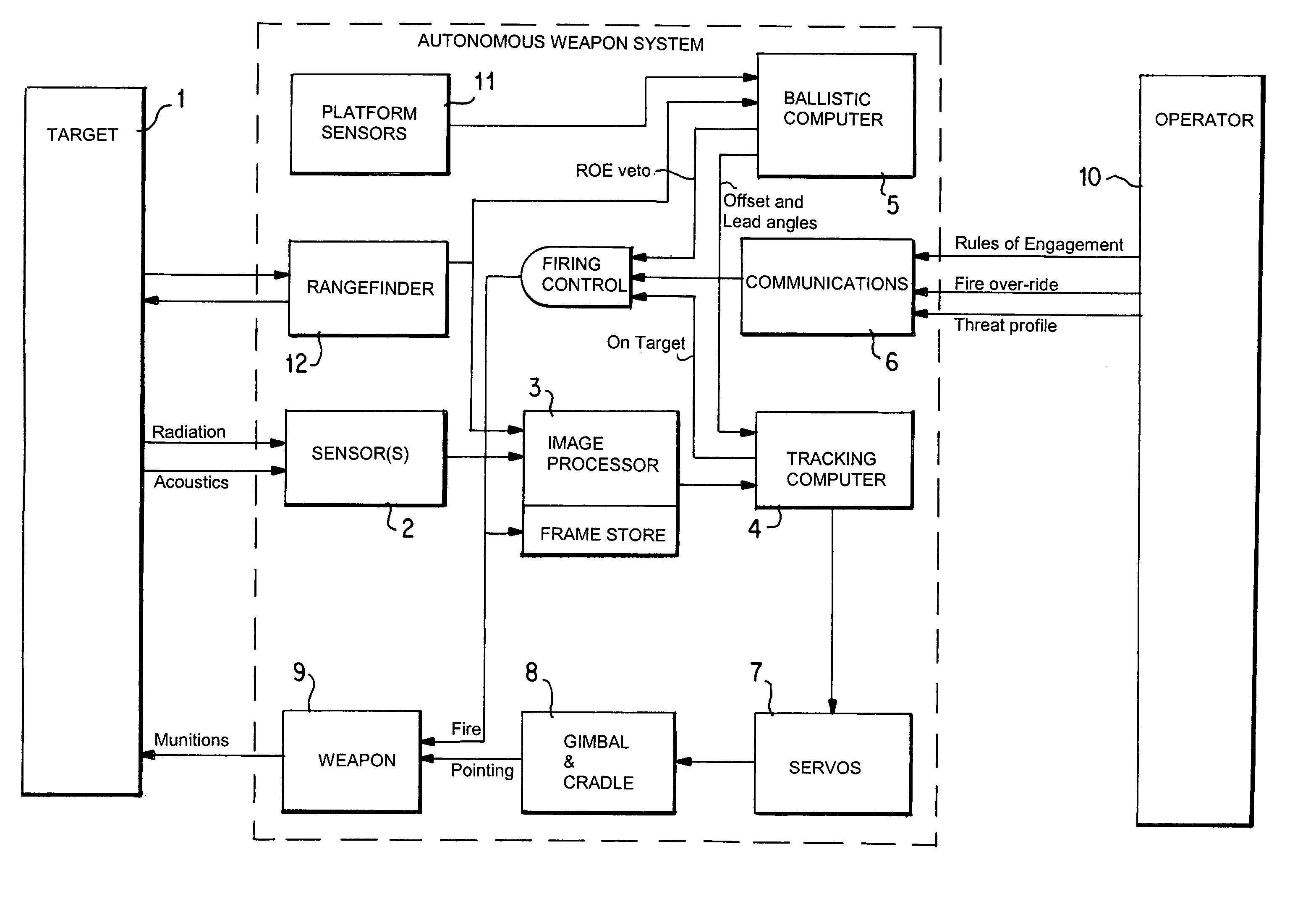
[0025]Preferably, the AWS has track processing means to process said acquired images or data to determine the correct pointing angles for the weapon to compensate for platform or target motion. The track processing means may include one or more digital signal processors that obtain information relating to target motion relative to the weapon or its platform from one or more locations within one or more fields of view of each sensor that the target(s) occupy, and / or from the apparent motion over time of the target(s) in such fields of view. The accuracy of the track processing means is preferably enhanced by resolving all motion to a local quasi-inertial reference frame so that the track processing means has access to data from such a frame, either within the AWS or external to it.
[0045]IFF compatibility. Casualties from friendly fire are a major problem for modem combatants, largely due to the pace of modem combat and reduced reaction times. Autonomous weapon systems potentially exacerbate this problem, if deployed with aggressive rules of engagement. However, the invention includes electronic support for an external IFF (identify friend or foe) firing veto, with virtually instantaneous response. This means that in addition to the applicable rules of engagement and the remote operator firing veto, the weapon can accept a real-time firing veto based on any IFF protocol in use at the time of deployment.

Problems solved by technology

The advantages of remote operation (e.g. of machine guns during trench warfare) were observed in the early 20th century, but the technology did not exist to allow remote operation without substantially degrading overall combat effectiveness.
Notwithstanding the advantages of remote weapon systems, their shortcomings include:Poor accuracy.
The use of manual weapon pointing, even if stabilized for weapon platform motion, does not allow optimum use of weapons.
The most common and inexpensive direct-fire weapons have inherent accuracy that exceeds the ability of human gunners to aim the weapon.Poor ergonomics.
This reduces the effectiveness of the weapon system.Poor stabilization.
This results in costly systems that do not take into account movement of the target, and are of limited use in realistic combat situations involving target motion.

Method used


Image

  • Autonomous weapon system
  • Autonomous weapon system
  • Autonomous weapon system

Examples


Embodiment Construction

(a) System Overview: AWS

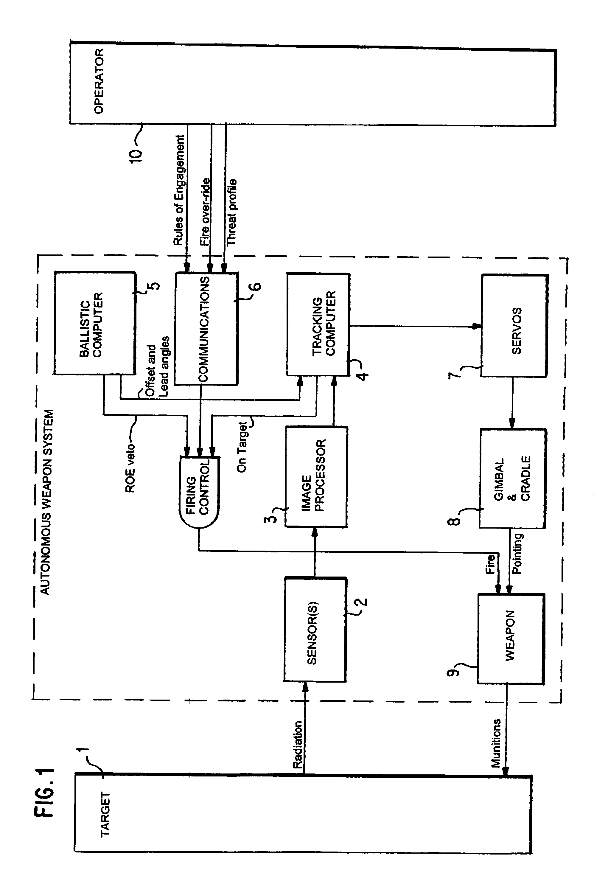
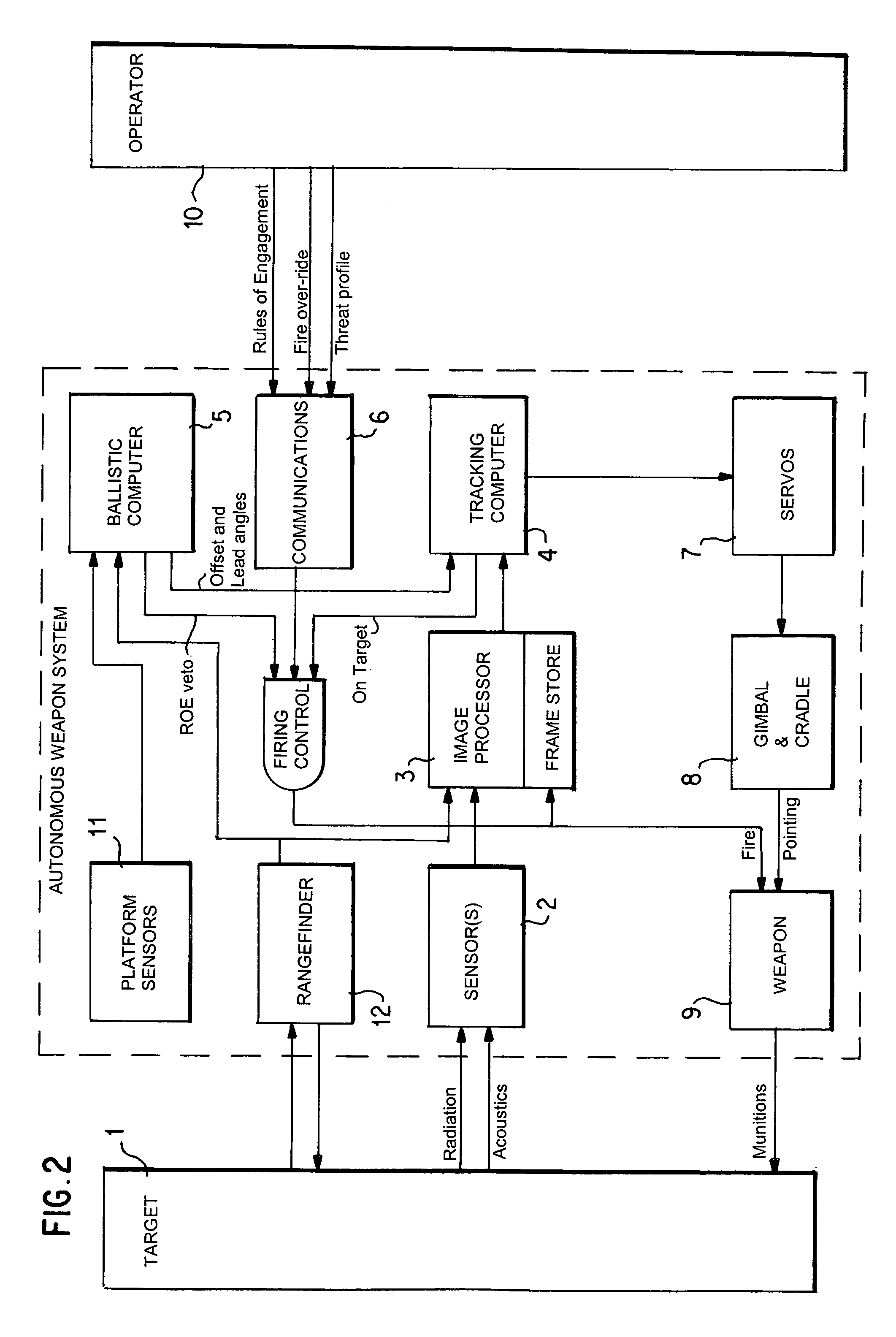
[0053]Electro-magnetic energy reflected or radiated by the target [1] is detected by the imaging sensors [2]. Typical imaging sensors include CCD or CMOS cameras, intensified CCD or CMOS cameras, high quantum efficiency CCD or CMOS cameras operating at very low light levels, thermal imaging cameras, and bolometric thermal sensors.

[0054]A single imaging sensor is sufficient to provide an image that meets the basic requirements for the AWS to operate. However multiple sensors operating in both visible and infrared spectrums, and with their combined data used to make decisions in respect of target detection, provide improved performance.

[0055]The image(s) from the sensor(s) are passed to the image processor [3] where they are digitally enhanced and processed to detect and classify objects of interest.

[0056]Once the image processor [3] has detected and classified a target, its position and motion relative to the boresight of the sensor system is determined on the...


PUM


Abstract

An autonomous weapon system including weapon (9) and weapon mounting system (7, 8) operable to point the weapon (9) in accordance with input control signals. The weapon system includes a sensor (2) to acquire images and other data from a target zone and an image processor (3) to process acquired image data and identify potential targets (1) according to predetermined target identification criteria. Targeting system (4, 5) provides input control signals to the weapon mounting system (7, 8) to point the weapon (9) for firing at potential targets (1). A control system operates targeting system (4, 5) and fires the weapon (9) at selected targets (1) according to a predetermined of rules of engagement. The rules of engagement include combat, peacekeeping or policing scenarios. Remotely located operator (10) may amend the rules of engagement, or override the control system as required.

Description

FIELD OF THE INVENTION[0001]This invention relates generally to autonomous direct fire weapon systems, being weapon systems that engage targets with no requirement for human intervention or support at the time of engagement, and with direct fire, meaning that a line-of-sight exists between the weapon and the target.BACKGROUND ART[0002]Direct fire weapons are weapons that require a line-of-sight between the weapon and the target. Examples of direct fire weapons include rifles, machine guns, canon, short range missiles and directed energy weapons. Examples of indirect fire weapons include artillery, mortars, and long-range missiles.[0003]Until the middle of the 20th century, direct fire weapons were fired manually by a gunner positioned directly behind the weapon. The advantages of remote operation (e.g. of machine guns during trench warfare) were observed in the early 20th century, but the technology did not exist to allow remote operation without substantially degrading overall comb...

Claims


Application Information

Patent Timeline
IPC IPC(8): F41G3/08F41G3/00F41G3/06F41G3/12F41G3/16F41G3/22
CPCF41G3/06F41G3/12F41G3/165F41G3/22F41A23/24
Inventor GREENE, BEN A.GREENE, STEVEN
Owner ELECTRO OPTIC SYST
Learn More