
Slug pulling preventing tooling die

a tooling die and slug technology, applied in metal-working equipment, perforating tools, metal working equipment, etc., can solve the problems of slug pulling, slug retention or slug pulling as it is commonly known, a significant problem, and the down time of the machine as well as the material, and the damage of the tool and the machin

Active Publication Date: 2007-05-01
DEGELMAN IND LP
View PDF16 Cites 14 Cited by
  • Summary
  • Abstract
  • Description
  • Claims
  • Application Information

AI Technical Summary

Benefits of technology

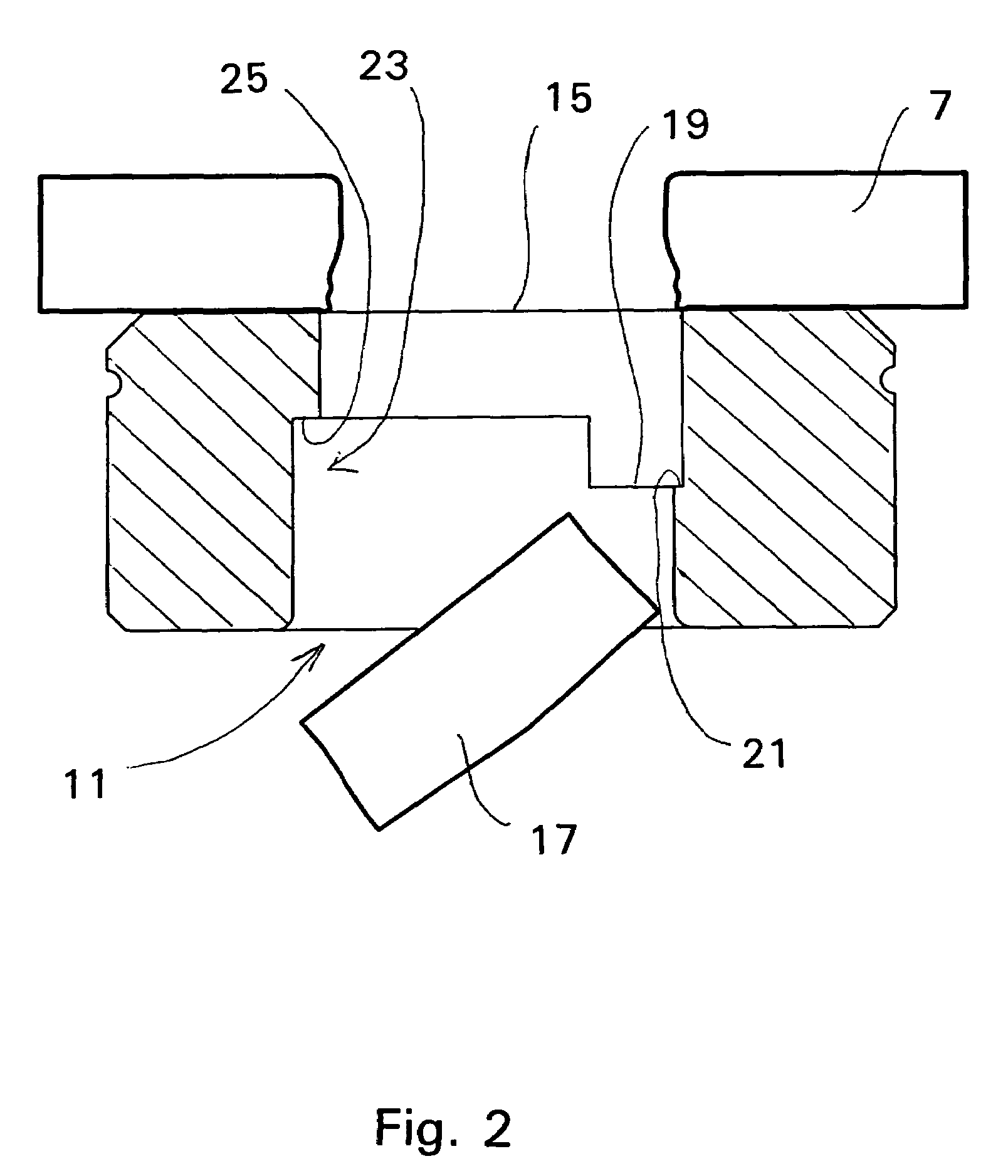
"The present invention aims to solve the problem of slug retention and slug pulling in punch and die machines when creating holes in metal plates. The invention provides a partially circumferential ridge and a relief area formed substantially horizontally relative to the longitudinal axis of the die bore to facilitate the elimination of slug retention by the punch. The ridge and land are formed by providing partially offset die bores or non-concentrically machined top and bottom die bores. The offset bore is formed by initially forming a larger diameter offset lower bore section and then forming a slightly smaller top bore to overlap the lower bore section and create a relative longitudinal spacing between the ridge area and the relief area that forces the slug to deflect or tilt thereby breaking any bond between the slug and the tooling punch. The invention also provides a long lasting, wear resistant die that is economical and can be easily mass produced and the performance of the die with respect to slug pulling is heightened the more the die is used due to wear off the sharp edges formed by the offset die bores."

Problems solved by technology

Slug retention or slug pulling as it is commonly known is a significant problem with such tool and die apparatus.
Slug pulling will cause machine down time as well as material, tool and machine damage.
A number of factors can cause slug pulling.
Lighter oils i.e. generally oils of lower viscosity, may reduce the vacuum effect to some extent, but slug pulling still occurs.
Furthermore, lighter oils vaporize and are messy.
Also, as the punch begins to wear, a raised butt is created on top of the slug that can “hug” or wrap itself around the punch adhering to the punch to cause slug pulling.
It is also possible for the punch to become magnetized, thus causing an undesired adherence of the slug to the slug face.
None of these solutions have been shown to be particularly effective as slug pulling can still occur, and as the internal ridges or pressure points wear, the slug pulling problem gets worse.

Method used


Image

  • Slug pulling preventing tooling die
  • Slug pulling preventing tooling die
  • Slug pulling preventing tooling die

Examples


Embodiment Construction

[0021]A punch and die machine, as well known in the art, is provided with a punch and a die for forming holes in metal plate. Observing FIG. 1, a punch 1 is shown positioned above, and relatively spaced above a die 3 and metal plate 7. The punch 1 is provided with a point 5 extending downward to define a longitudinal axis A along which the punch 1 generally travels in a substantially vertical, or up and down motion. The point 5 has a diameter which is substantially the same size as a hole to be formed in the metal plate 7, and at a free end of the point 5 a substantially flat, horizontally aligned and relatively flat face 9 is formed to directly contact and cut the metal plate 7.

[0022]The die 3 is positioned generally below the punch 1, and the die bore 11 is provided with a diameter which is at least slightly larger than the point 5 of the punch 1 to permit the face 9 and point 5 to penetrate into the die bore 11 along the longitudinal axis A. As is well understood by those in the ...


PUM

PropertyMeasurementUnit
viscosityaaaaaaaaaa
frictionaaaaaaaaaa
pressureaaaaaaaaaa

Abstract

A punch and die tooling apparatus commonly used by metal fabricators for creating holes, passages and cavities in metal plate, the die having a unique internal bore which relieves the problem of slug pulling to ensure that a slug punched out of a metal sheet is not retained on the punch face to interfere with further operation of the apparatus. The die is provided with a substantially horizontal ridge and a corresponding horizontal land and relief space formed within the bore to facilitate tipping of the slug relative to the punch and thereby break any attachment between the slug and the punch face which causes slug pulling.

Description

FIELD OF THE INVENTION[0001]The present invention relates to a punch and die tooling apparatus commonly used by metal fabricators for creating holes, passages and cavities in metal plate. In particular, the present invention relates to a die for such an apparatus having a unique internal bore which relieves the problem of slug pulling, i.e. ensures that a slug punched out of a metal sheet is not retained on the punch face to interfere with further operation of the apparatus. More specifically, the die is provided with a substantially horizontal ridge and a corresponding horizontal land and relief space formed within the bore to facilitates tipping of the slug relative to the punch and thereby break any attachment between the slug and the punch face which causes slug pulling.BACKGROUND OF THE INVENTION[0002]Punch and dies have been used for decades by metal fabricators as a common process for creating holes in metal plate. The die usually has a surface and above defining a cutting ed...

Claims


Application Information

Patent Timeline
Patent Type & Authority Patents(United States)
IPC IPC(8): B26F1/14B21D28/34B26D1/00B26D3/00
CPCB21D28/145B21D28/34Y10T83/9437Y10T83/9416Y10T83/04Y10T83/2218Y10T83/9425Y10T83/9423
Inventor ELYNUIK, MORRIS
Owner DEGELMAN IND LP
Learn More