
Cooling arrangements for integrated electric motor-inverters

a technology of integrated electric motors and cooling arrangements, which is applied in the direction of domestic cooling devices, indirect heat exchangers, lighting and heating devices, etc., can solve the problems of temperature changes in inverters and problems affecting the packaging of inverters with motors

Active Publication Date: 2007-05-01
PARKER INTANGIBLES LLC +1
View PDF2 Cites 82 Cited by
  • Summary
  • Abstract
  • Description
  • Claims
  • Application Information

AI Technical Summary

Benefits of technology

The patent describes a cooling arrangement for components of an inverter circuit used in electric vehicles. The arrangement includes a housing with a compartment containing the components, which is connected to an electric traction motor. The compartment is filled with a dielectric coolant that is dispensed into the space containing the components by a pump. The coolant is then cycled back over the components to absorb heat. The arrangement also includes a control to monitor and power the pump based on the cooling requirements of the components. The cooling arrangement can be used in combination with other cooling systems for other components, such as fuel cell stacks or gas-powered traction engines. The dielectric coolant is a mixture of polypropylene glycol methyl ether and hexamethyldisiloxane, and has a phase change point to absorb a significant amount of heat before evaporating. The cooling arrangement also includes a condenser to convert the vaporized coolant back to liquid coolant before recycling it onto the components.

Problems solved by technology

Fluctuations in power demand cause temperature changes in the inverters connected to the traction motors.
In accomplishing optimal use of space, attempts are made to organize related components into modules, however packaging inverters with motors present a problem because inverters have different cooling requirements.

Method used


Image

  • Cooling arrangements for integrated electric motor-inverters
  • Cooling arrangements for integrated electric motor-inverters
  • Cooling arrangements for integrated electric motor-inverters

Examples


Embodiment Construction

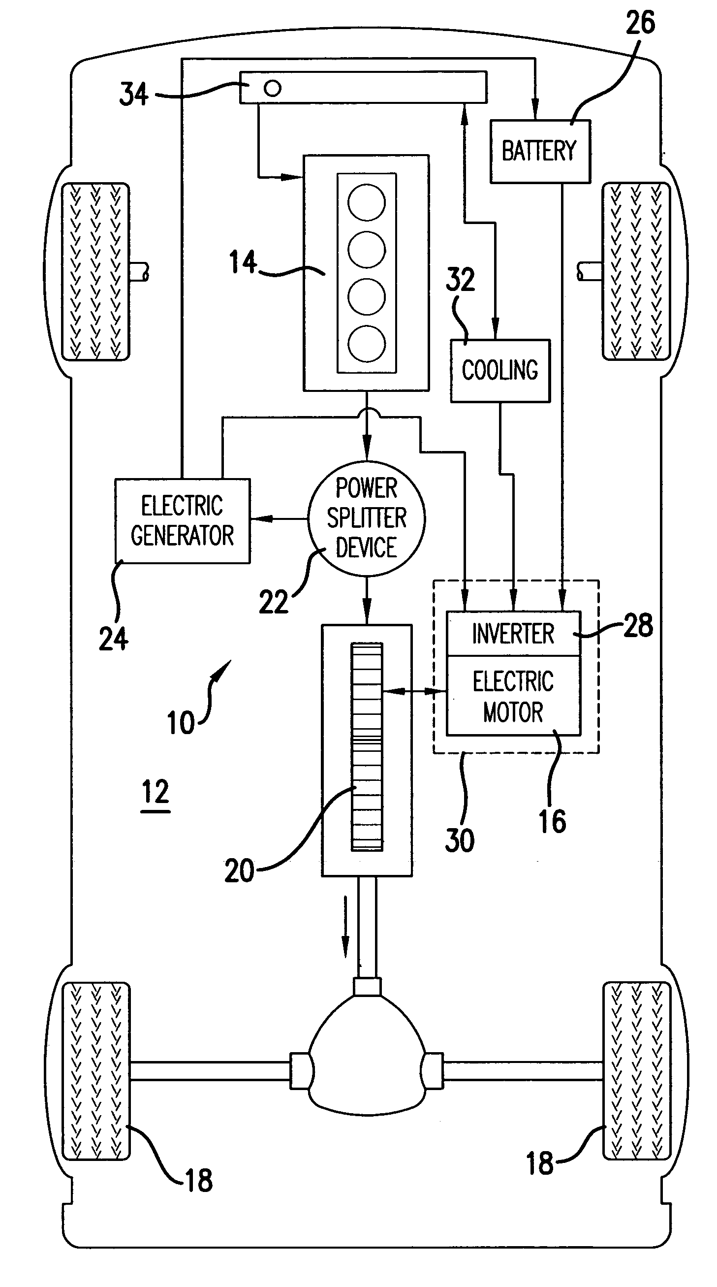
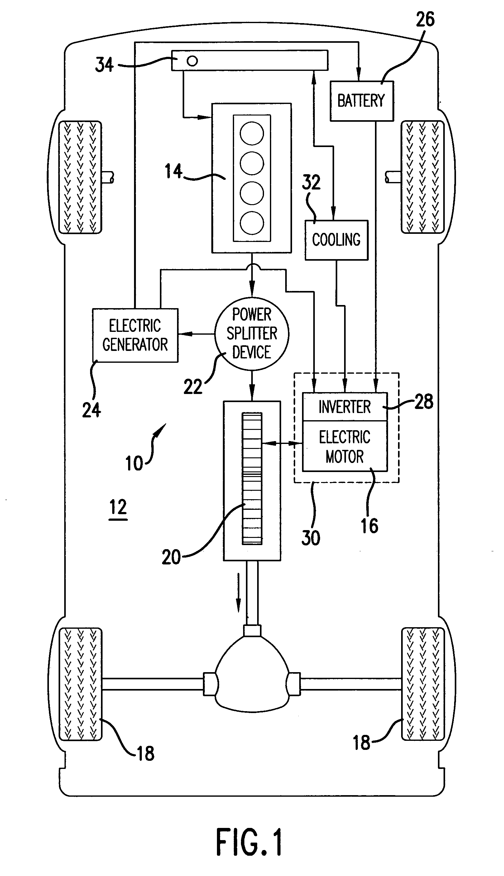
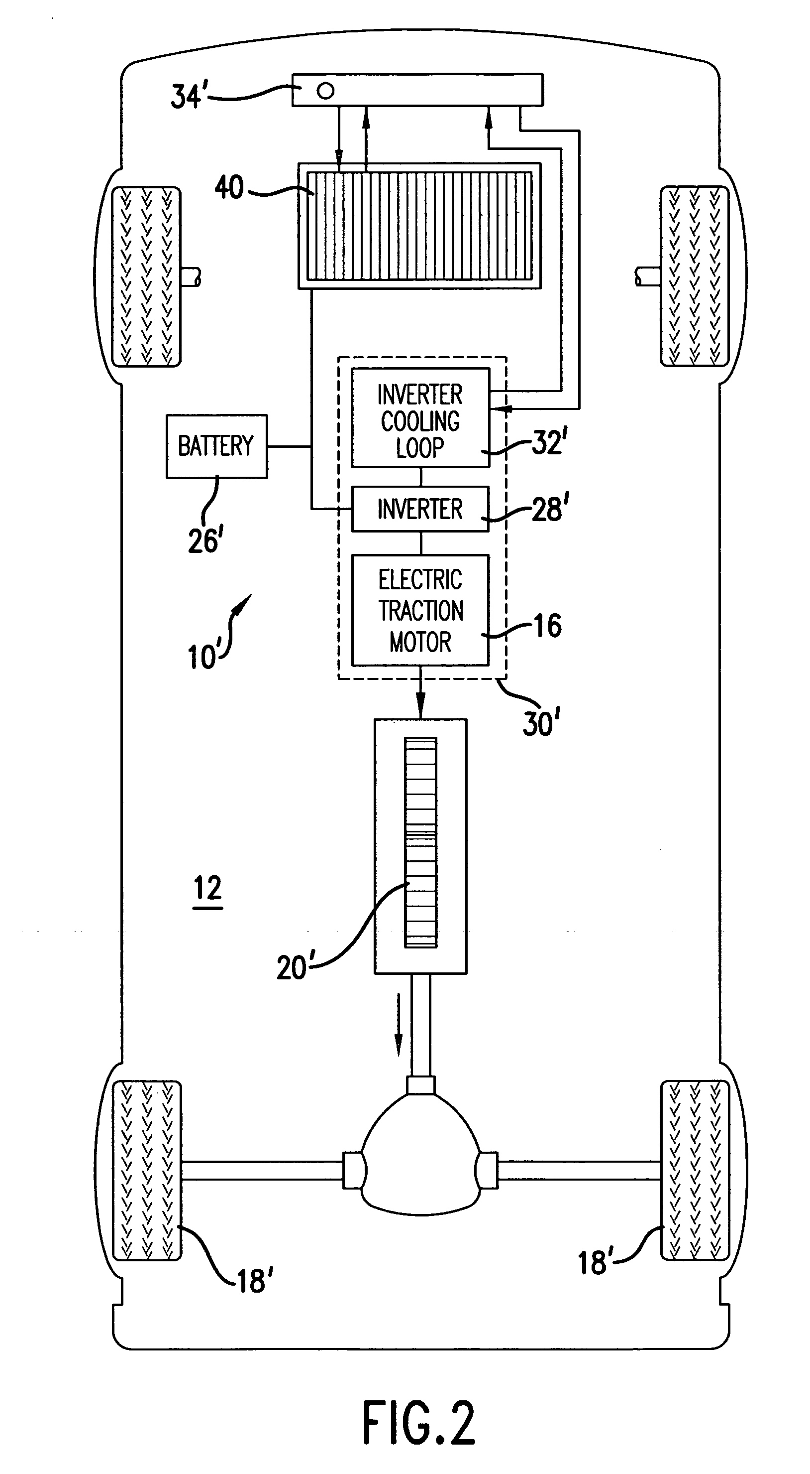
[0025]Referring now to FIG. 1, there is shown an example of a gas-electric drive 10 for powering a vehicle 12 utilizing an internal combustion engine 14 and an electric traction motor 16 to drive, through a transmission 20, wheels 18 of the vehicle. A power splitter 22 determines whether the internal combustion engine 14 or the electric motor 16 drives the transmission 20, or whether the transmission 20 or internal combustion engine drives an electric generator 24. In another embodiment, the generator 24 is mounted next to the electric traction motor 16 and cooled with the same arrangement as the traction motor. The electric generator 24 charges a battery 26 and / or provides current to an inverter 28 that delivers current to the electric traction motor 16. In accordance with the present invention, the electric traction motor 16 and inverter 28 are configured as a modular unit 30. This provides an opportunity for a reduction in the space consumed by the electric traction motor 16 and ...


PUM


Abstract

In order to provide a modular arrangement, an inverter for an electric traction motor used to drive an automotive vehicle is positioned in proximity with the traction motor. The inverter is located within a compartment adjacent to one end of the electric traction motor and is cooled in a closed system by spraying a liquid coolant directly onto the inverter. The liquid coolant absorbs heat from the inverter and is cooled by a heat exchange arrangement comprising a reservoir with pipes carrying a second coolant from the radiator of the automotive vehicle. In a preferred embodiment, the coolant is collected from the inverter in an annular reservoir that is integral with the compartment containing the inverter. In accordance with one embodiment of the cooling arrangement, heat from the inverter vaporizes the liquid coolant by absorbing heat from the inverter during a phase change from a liquid to a vapor. The vaporized coolant is condensed by a circulating second coolant in pipes connected to the vehicle's radiator through a condenser that is preferably coaxial with the motor and the annular reservoir, which annular reservoir in the second embodiment collects overspray liquid coolant. In order to avoid degrading the inverter, the coolant is a dielectric fluid.

Description

FIELD OF THE INVENTION[0001]The present invention is directed to cooling arrangements for integrated electric motor-inverters. More particularly, the present invention is related to cooling arrangements for integrated electric motor-inverters wherein the motor is a traction motor used to drive electric vehicles such as, but not limited to, gas-electric hybrid vehicles and fuel cell powered electric vehicles.BACKGROUND OF THE INVENTION[0002]Vehicles which utilize electric traction motors to drive wheels of a vehicle, whether the electric motor is in a gas-electric hybrid vehicle or a fuel cell powered vehicle typically use a three-phase AC motor coupled with an inverter that converts direct current from a power source to alternating current. The inverter circuitry generally comprises IGBTs (insulated gate bipolar transistors) mounted on a DBC (direct bonded copper) substrate. The DBC has integrated bus bars, and with a circuit card and signal connector provides a power electronics pa...

Claims


Application Information

Patent Timeline
Patent Type & Authority Patents(United States)
IPC IPC(8): F25D23/12B60K6/26
CPCF28D15/00F28D15/0266H02K9/19H02K11/0073H05K7/20936B60K6/26B60K2001/003H02K11/33
Inventor NAGASHIMA, JAMES M.CONROY, KARL D.OSTROM, ERIC R.SMITH, GREGORY S.JOHN, GEORGETANG, DAVIDWARD, TERENCE G.
Owner PARKER INTANGIBLES LLC
Learn More