
Excitation of switched reluctance motors

a technology of switched reluctance and motor, applied in the direction of motor control for motor oscillation damping, synchronous motor starter, starter arrangement, etc., can solve the problems of increasing the burden on the supply, unsuitable single-pulse mode, and being too expensive for the majority of applications

Inactive Publication Date: 2007-04-24
NIDEC SR DRIVES
View PDF40 Cites 11 Cited by
  • Summary
  • Abstract
  • Description
  • Claims
  • Application Information

AI Technical Summary

Benefits of technology

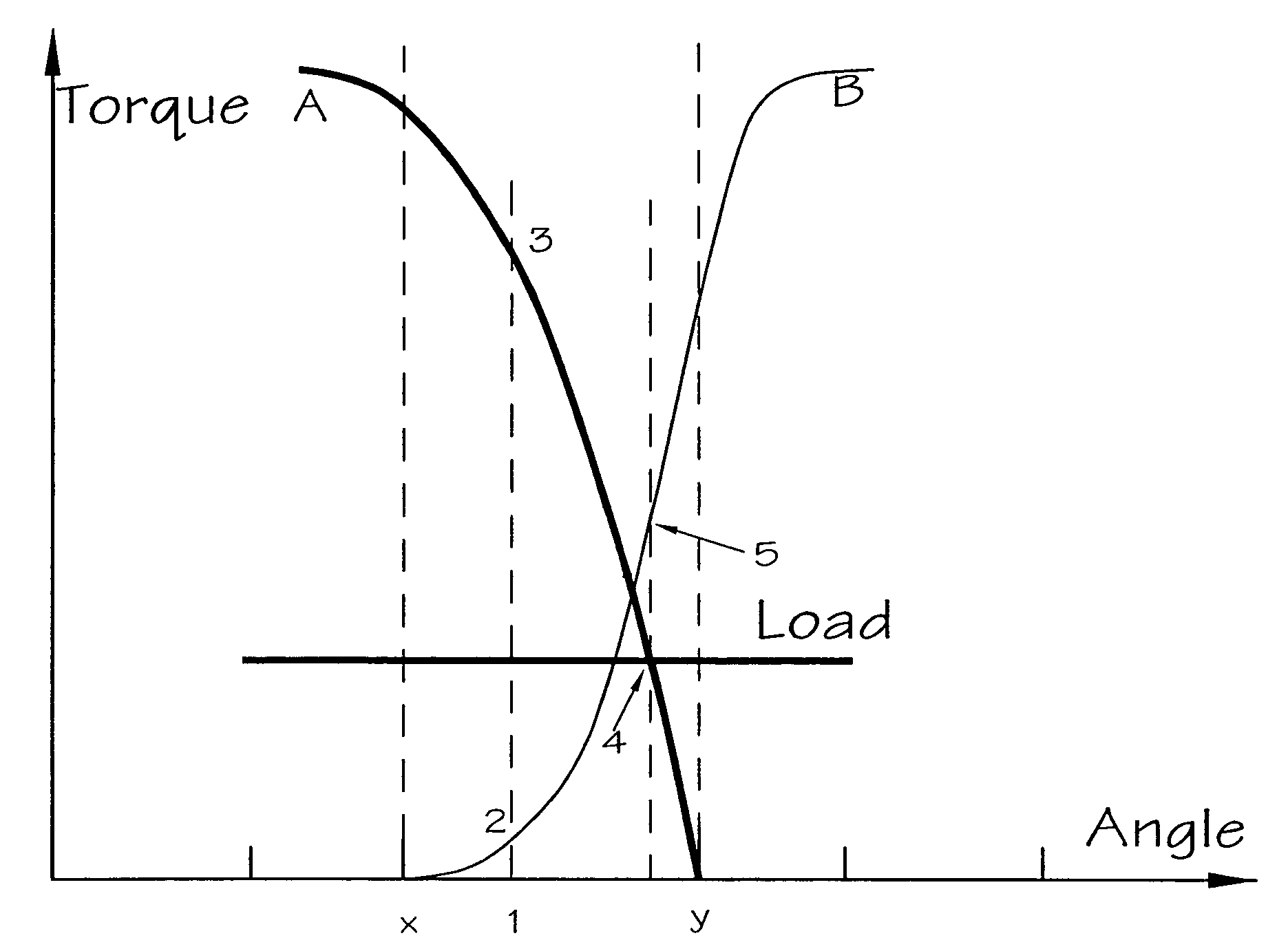
[0017]There is a need for a starting system according to embodiments of the invention which can start a high inertia load with a maximum amount of torque for a minimum current consumption.

Problems solved by technology

While a high-resolution resolver could be used, these are relatively expensive and unnecessarily complex for the majority of applications.
At zero and low speeds, however, the single-pulse mode is not suitable, due to the high peak currents which would be experienced, and the chopping mode is used.
For a given excitation level, operation in this manner considerably increases the burden on the supply.
While in some applications the absolute size of the DC link current is secondary to torque output, in other applications there is extreme sensitivity to the DC link current, as the source may have limited capacity.
Typically, such limitations are found in sites which have stand-alone generation, or in mobile situations such as automotive, marine or aerospace applications.
These sites are unsuited to drives in which there is simultaneous conduction by two phases because of the increased current demand.
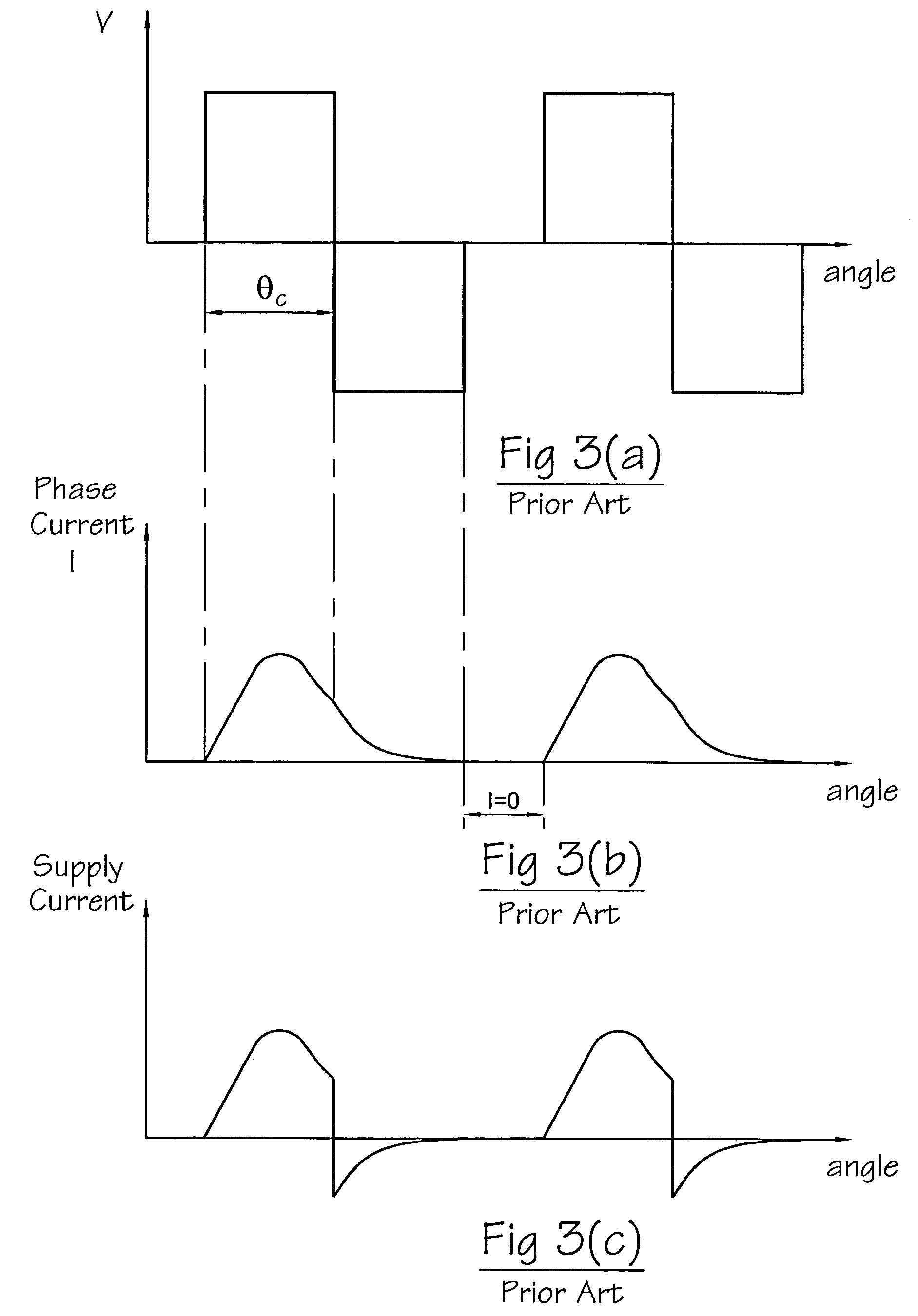
In the meantime, the current in the freewheeling phase decays as a function of time, not rotor position, so there is a significant risk that the current (and hence the torque) will decay to zero before the rotor has reached a position where the next phase to be energized can supply sufficient torque on its own.

Method used


Image

  • Excitation of switched reluctance motors
  • Excitation of switched reluctance motors
  • Excitation of switched reluctance motors

Examples


Embodiment Construction

[0040]Embodiments of the invention are implemented in this embodiment in a drive system such as that shown in FIG. 1. Switching circuits for each of the phases as shown in FIG. 2 optionally are used, but it is not necessary for the switching circuit to have freewheeling capability. According to embodiments of the invention to be described, the control strategy is adapted to exploit the capabilities of the chosen switching circuit by programming of the controller 14.

[0041]A typical RPT for the 3-phase drive of FIG. 1 is shown schematically in FIG. 5. The three sensors are shown with 120° mechanical offset, but can have any offset which equals 120° electrical. The schematic shown has teeth with a mark:space ratio of unity. In practice, this may be varied slightly to accommodate any non-ideal characteristics of the sensors, e.g. beam width in an optical sensor or fringing in a Hall-effect sensor, so that the final signal from the RPT is at or acceptably near unity mark:space. The outpu...


PUM


Abstract

A switched reluctance drive is supplied from a power source. The phases of the machine are controlled by a current controller which uses an excitation strategy to minimize the supply current drawn for a particular output. The strategy alternates the excitation between two phases for a given time until the rotor moves to a desired position. A method of starting a switched reluctance motor having a stator with at least two phases, a moveable part, and a position transducer includes determining from transducer output a plurality of phases that are available to produce force in a desired direction, energizing a first phase of the available phases for a predetermined time period that is independent of the transducer output, and energizing a second phase of the available phases after energization of the first phase is initiated.

Description

CROSS-REFERENCE TO RELATED APPLICATION[0001]The subject matter of this application is related to the subject matter of British Patent Application No. GB 0310491.6, filed May 7, 2003, priority to which is claimed under 35 U.S.C. § 119 and which is incorporated herein by reference.BACKGROUND OF THE INVENTION[0002]1. Field of the Invention[0003]Embodiments of this invention relate to the excitation of switched reluctance motors. In particular, they relate to excitation to reduce the supply current drawn for a particular output.[0004]2. Description of Related Art[0005]The characteristics and operation of switched reluctance systems are well known in the art and are described in, for example, “The characteristics, design and application of switched reluctance motors and drives” by Stephenson and Blake, PCIM'93, Nürnberg, 21–24 Jun. 1993, incorporated herein by reference. FIG. 1 shows a typical switched reluctance drive in schematic form, where the switched reluctance motor 12 drives a lo...

Claims


Application Information

Patent Timeline
Patent Type & Authority Patents(United States)
IPC IPC(8): H02P1/46H02P6/22H02P25/08
CPCH02P25/088H02P6/22H02P25/098
Inventor TURNER, MICHAEL JAMESSYKES, PAUL ANDREW
Owner NIDEC SR DRIVES
Learn More