
Spiral wound filtration membrane cartridge with chevron seal

a technology of filtration membrane and chevron seal, which is applied in the direction of cartridge filter, filtration separation, separation process, etc., can solve the problemsdeterioration of adhesive or potting composition, etc., and achieves the effect of reducing the effectiveness of seal, facilitating cartridge replacement, and easy control of the size and shape of this portion of the apparatus

Inactive Publication Date: 2007-04-24
MILLIPORE CORP
View PDF12 Cites 51 Cited by
  • Summary
  • Abstract
  • Description
  • Claims
  • Application Information

AI Technical Summary

Benefits of technology

[0008]The seal construction of this invention provides substantial advantages over the use of adhesive or potting compositions including the fact that it can be completely installed immediately rather than waiting approximately 2–3 days for complete setting of the composition. In addition, the adhesive or potting composition deteriorates over time, producing extractables and reducing the effectiveness of the seal. Furthermore, the seal construction of this invention is not limited to specific adhesive compositions thereby permitting the use of a wide variety of materials for forming the seal construction. Finally, the seal construction of this invention is more robust than the seal construction of the prior art since it does not deteriorate significantly over time.
[0009]The filtration cartridge is formed by spirally winding one of a plurality of V-shaped filtration membranes, porous feed screens and porous permeate screens about a central tube having holes which are in selective fluid communication with the permeate screens. The filtration cartridge can be wrapped about its entire outside surface with a fluid permeable layer such as the permeate screen or feed screen and is tightly fit within the outer tube. The outer tube, in turn, is fit within the housing. One end of the outer tube is provided with a retentate recovery means. One or both ends are provided with permeate recovery means. The outer tube and the fluid feed means permit construction of the portion of the cartridge apparatus that fits into the outer tube in a controlled manufacturing environment so that the size and shape of this portion of the apparatus can be controlled easily. This, in turn, provides ease of cartridge replacement in the field.

Problems solved by technology

In addition, the adhesive or potting composition deteriorates over time, producing extractables and reducing the effectiveness of the seal.

Method used


Image

  • Spiral wound filtration membrane cartridge with chevron seal
  • Spiral wound filtration membrane cartridge with chevron seal
  • Spiral wound filtration membrane cartridge with chevron seal

Examples


Embodiment Construction

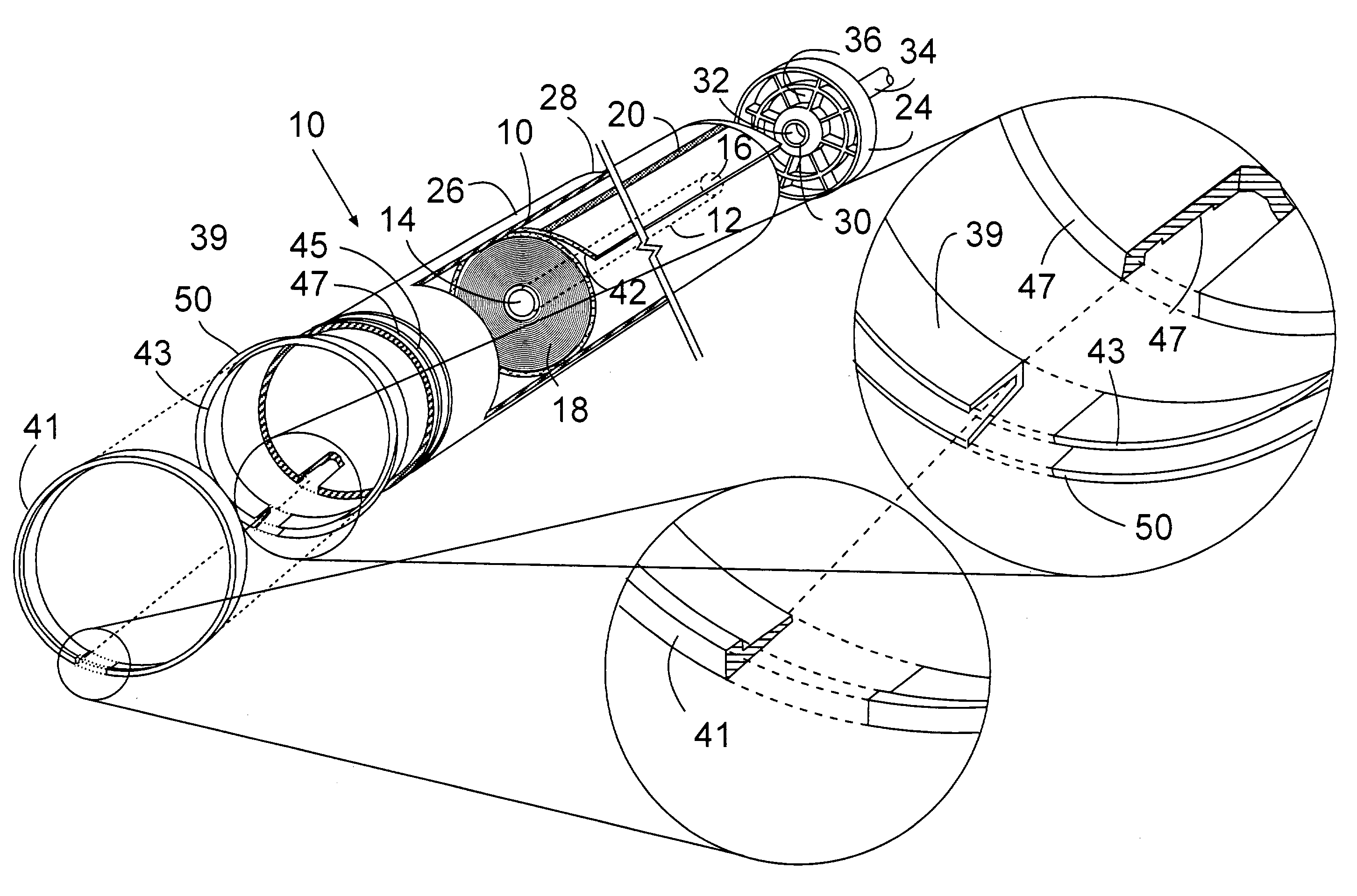
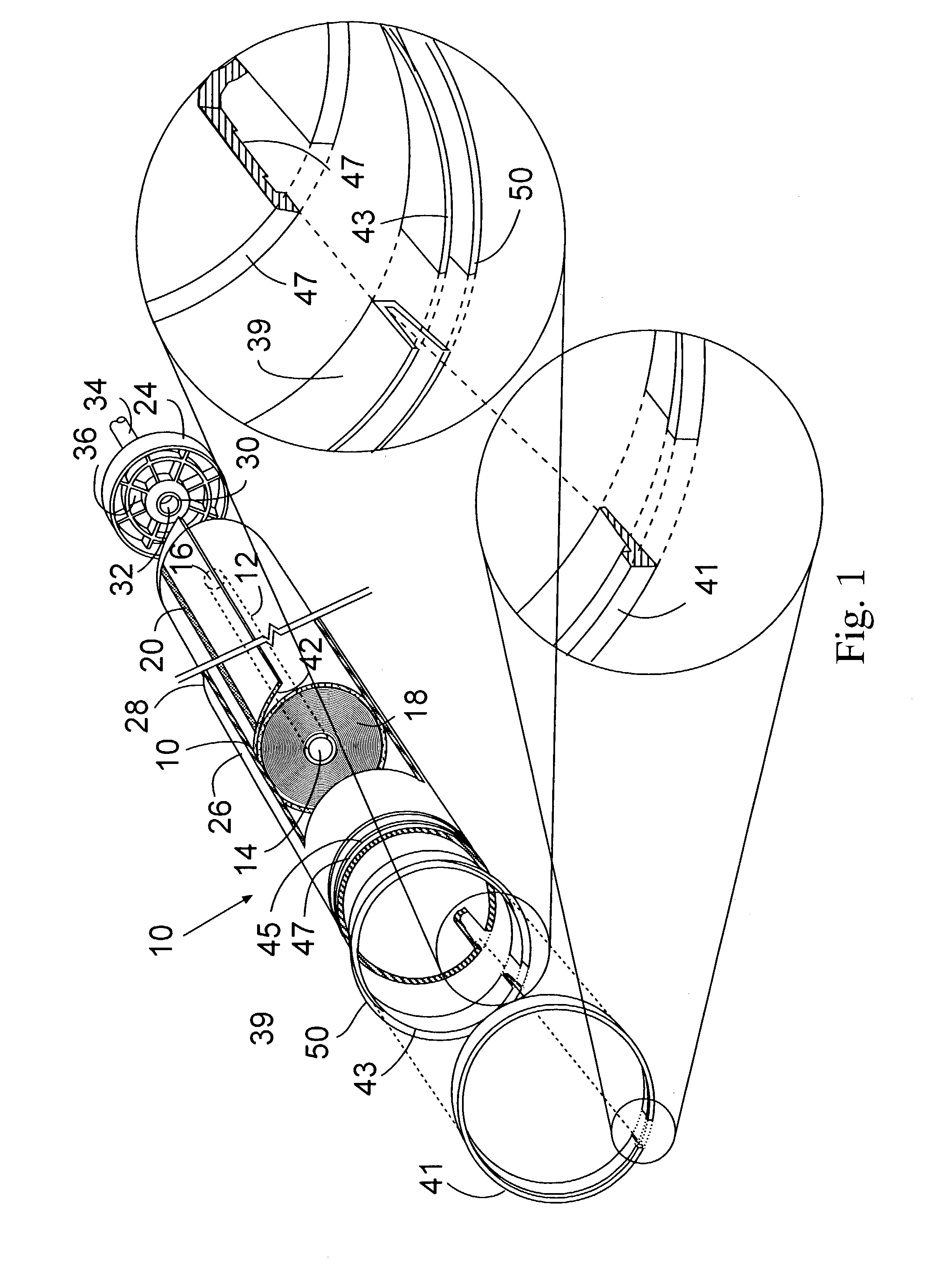
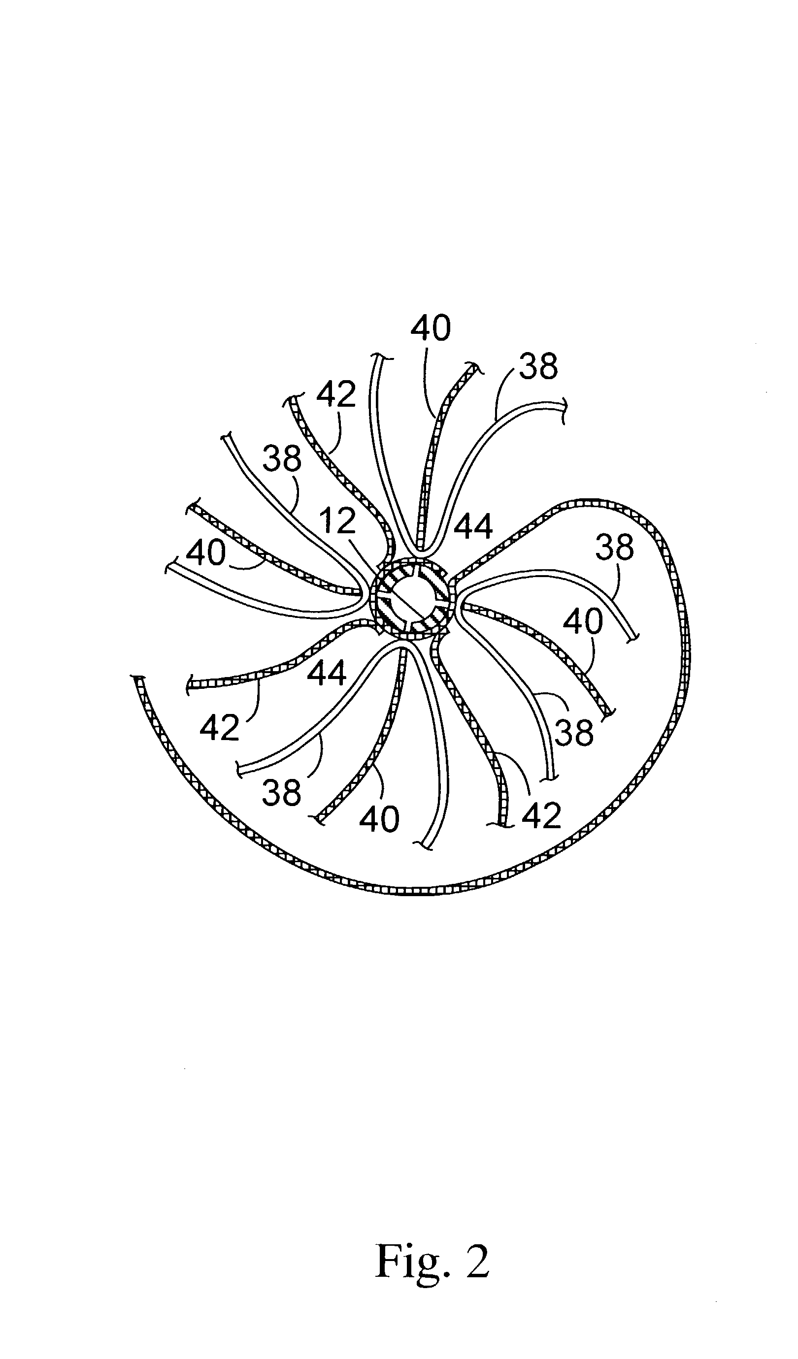
[0014]Referring to FIG. 1, the spiral wound apparatus of this invention 10 (excluding the outer housing and fluid feed means) includes a central tube 12 having an exit 14 and an exit 16 for recovering permeate from the apparatus 10. Optionally, one of the exits 14 or 16 can be blocked so that the permeate is recovered only from one exit 14 or 16. The spiral wound filtration cartridge 18 is comprised of the elements shown in FIG. 2 which will be described herein below. The spiral wound portion 18 includes an axial seal 20 which serves to prevent retentate and permeate from mixing. An end plate 24 is sealed to rigid solid outer tube 26 about the periphery 28 and to the periphery of exit 16 at the inner periphery 30 of end plate 24. The end plate 24 is not required for use in this invention. Exit 32 is in fluid communication with central tube 12 and permeate recovery conduit 34. Retentate exits form spiral surface 33 of spiral cartridge 18 through exit holes 36 in end plate 24 and is r...


PUM

PropertyMeasurementUnit
Flexibilityaaaaaaaaaa

Abstract

A spiral wound filtration cartridge construction is provided which includes a cartridge positioned within a solid outer cylinder which, in turn is positioned within a solid outer cylinder which, in turn is positioned within a solid housing. Fluid flows within the space between the outer cylinder and housing is controlled by a ring and flexible chevron construction. The chevron construction includes outer peripheral holes, the sizes and number of which are set to determine by-pass flow.

Description

[0001]This application claims priority of Provisional Application Ser. No. 60 / 383,922 filed May 29, 2002.BACKGROUND OF THE INVENTION[0002]This invention relates to a spiral wound filtration cartridge construction utilized in fluid separation processes such as reverse osmosis or ultrafiltration. More particularly, this invention relates to a spiral wound filtration cartridge construction having a chevron seal construction with a partial feed bypass means which prevents fluid stagnation within and around the cartridge during use.[0003]Prior to the present invention, spiral wound filtration cartridges have been provided comprising a centrally positioned tube about which are wound membrane sheets and suitable permeate spacers and feed spacers. The membrane sheets are V shaped and the feed spacers are positioned within the shaped membrane while the permeate spacers are positioned outside the V shaped membranes. The feed spacers promote passage of feed fluid into the V shaped membrane and...

Claims


Application Information

Patent Timeline
IPC IPC(8): B01D63/10B01D63/12B01D63/00B01D61/10B01D61/20B01D65/00
CPCB01D61/10B01D61/20B01D63/10B01D65/00
Inventor ALMASIAN, JOSEPHDZENGELESKI, STEPHEN
Owner MILLIPORE CORP
Learn More