
Continuous alternating closed-open loop power control

a closed-loop power control and continuous alternating technology, applied in power management, amplifiers, semiconductor devices/discharge tubes, etc., can solve the problems of discontinuity, low transmit power, and low reliability of closed-loop power control at low transmit power

Active Publication Date: 2007-04-17
TELEFON AB LM ERICSSON (PUBL)
View PDF12 Cites 50 Cited by
  • Summary
  • Abstract
  • Description
  • Claims
  • Application Information

AI Technical Summary

Benefits of technology

This approach ensures compliance with relative transmit power requirements by minimizing power step discontinuities during transitions, allowing for accurate power control across varying power levels without violating absolute or relative power standards.

Problems solved by technology

Because power detectors have a limited dynamic range, wireless communication devices may be unable to accurately measure low transmit powers, causing closed-loop power control to become unreliable at low transmit powers.
However, because open-loop power control does not include any means for verifying the accuracy of the transmit power, open-loop power control may generate transmit powers that drift away from the desired transmit power, and therefore, violate the absolute power requirements.
However, because the open-loop transmit power is relatively undefined before the switch to closed-loop, the power step that occurs when switching from open-loop to closed-loop power control will also be relatively undefined, which may cause a discontinuity to occur during the transition.
Further, because a gain control signal during closed-loop power control may significantly differ from the gain control signal generated after switching from closed-loop to open-loop power control, a discontinuity may also occur when switching from closed-loop to open-loop power control.
These discontinuities may cause the power step between adjacent time slots to exceed the relative transmit power requirements during transitions between open-loop and closed-loop power control.

Method used


Image

  • Continuous alternating closed-open loop power control
  • Continuous alternating closed-open loop power control
  • Continuous alternating closed-open loop power control

Examples


Embodiment Construction

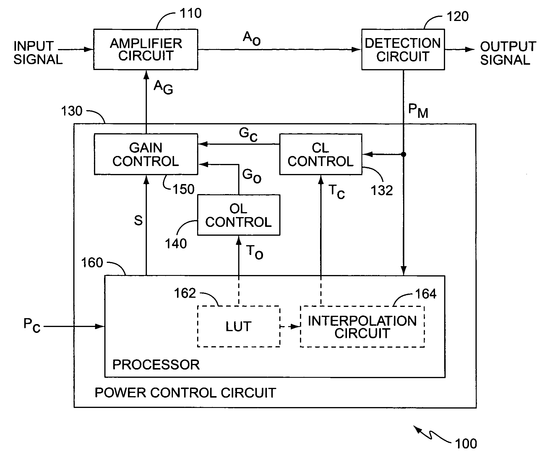
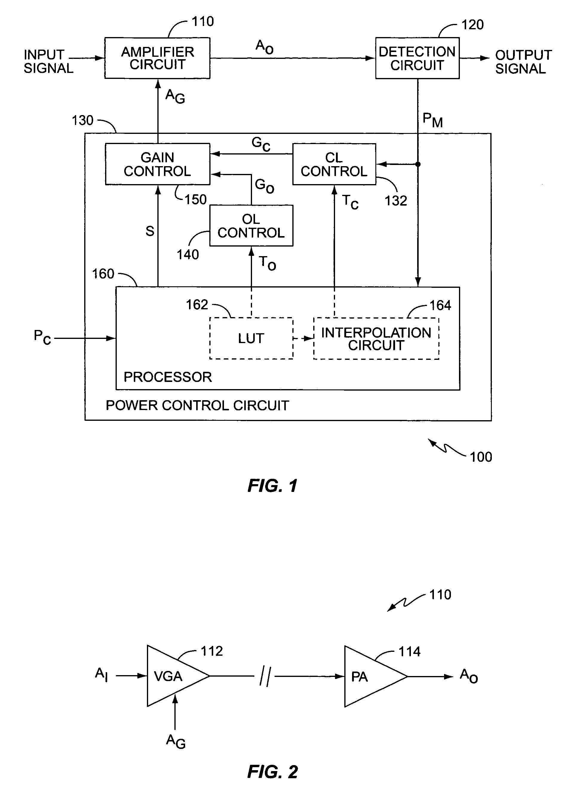
[0023]FIG. 1 illustrates a block diagram of an amplification system 100 according to one exemplary embodiment of the present invention. The following describes the invention in terms of an amplification system 100 in a wireless transmitter of a wireless communication device, such as a cellular telephone, satellite telephone, personal communication services (PCS) devices, personal data assistants (PDAs), palm top computers, pagers, etc. However, it will be appreciated that the present invention applies to any amplification system 100 within any electronic device requiring a controlled output power level. Further, while the following describes the invention in terms of a wireless communication device within a WCDMA system, those skilled in the art will appreciate that the present invention also applies to other wireless communication systems, such as Time-Division Multiple Access (TDMA) systems, Orthogonal Frequency Division Multiplexing (OFDM) systems, etc.

[0024]Amplification system ...


PUM


Abstract

The present invention comprises a method and apparatus for continuously, controlling a gain of an amplifier circuit while switching between open-loop and closed-loop power control. A control circuit controls the gain of the amplifier circuit during open-loop and closed-loop power control modes based on selected references. Before the switch from open-loop to closed-loop power control, the control circuit determines a closed-loop reference based on a power measured at the amplifier circuit output before the switch. After the switch, the control circuit controls the gain of the amplifier circuit based on the determined closed-loop reference. Before switching from closed-loop to open-loop power control, the control circuit generates a difference between a current open-loop reference and a previous open-loop reference. After the switch, the control circuit controls the gain of the amplifier circuit based on an open-loop gain control signal generated by applying the difference to a previous closed-loop gain control signal.

Description

[0001]This application claims priority to Provisional U.S. Patent Application 60 / 643,624 filed 13 Jan. 2005, which is incorporated herein by reference.BACKGROUND OF THE INVENTION[0002]The present invention generally relates to power control for wireless transmitters, and more particularly to variable gain amplifier circuits for wireless transmitters.[0003]Wireless communication systems use power control to reduce interference and increase system capacity while maintaining minimum signal quality standards. The capacity of wireless communication systems, i.e., WCDMA (Wideband Code Division Multiple Access) systems, relies heavily on the accurate implementation of uplink power control. Many wireless communication standards, such as 3GPP TS 25.101, include specific requirements for transmit power control accuracy within the wireless communication device. These device requirements include both absolute and relative accuracy transmit power requirements. The absolute requirements define a ...

Claims


Application Information

Patent Timeline
Patent Type & Authority Patents(United States)
IPC IPC(8): H03G3/10
CPCH04W52/08H04W52/52H04W52/225H04W52/228H04W52/221H04W52/10H03G3/20H04B7/005
Inventor GUSTAVSSON, BJORNAKERBERG, MARTIN
Owner TELEFON AB LM ERICSSON (PUBL)
Learn More