Eureka AIR delivers breakthrough ideas for toughest innovation challenges, trusted by R&D personnel around the world.

Valve operating mechanism with roller rocker arm, 4-cycle engine, and motorcycle having 4-cycle engine mounted thereon

a technology of operating mechanism and roller rocker arm, which is applied in the direction of valve drive, machine/engine, auxillary lubrication, etc., can solve the problems of disadvantageous heavyness of exhaust rocker arm and large size, and achieve the effect of reducing load and preventing buckling load

Active Publication Date: 2007-04-17
YAMAHA MOTOR CO LTD
View PDF8 Cites 16 Cited by
  • Summary
  • Abstract
  • Description
  • Claims
  • Application Information

AI Technical Summary

Benefits of technology

[0014]In order to overcome the problems described above, preferred embodiments of the present invention provide a valve gear that is capable of preventing a buckling load from being applied to a first rocker arm and decreases a load being borne by the first rocker arm so that the first rocker arm does not have to be reinforced and made larger.
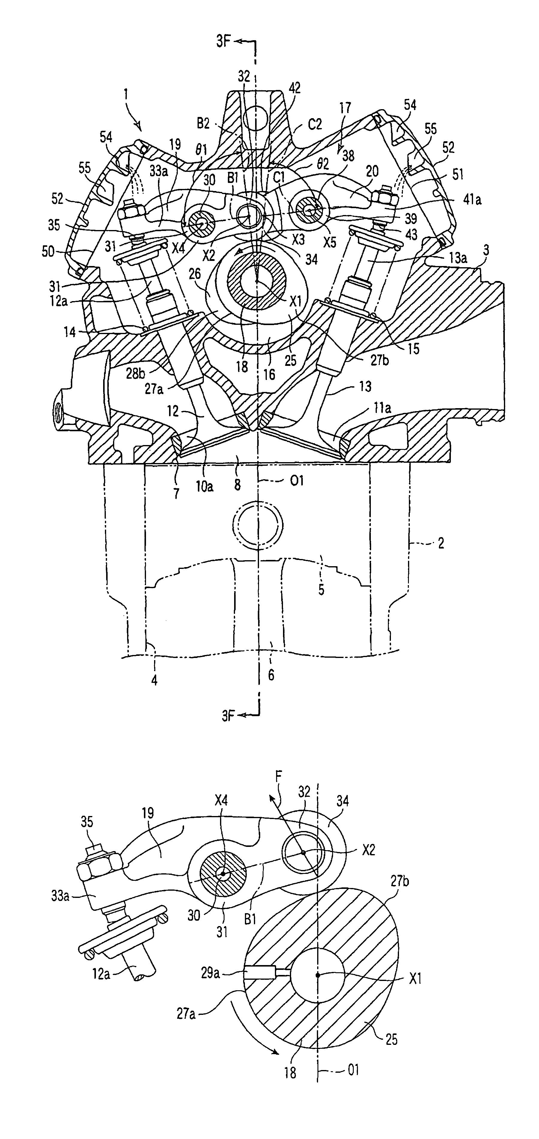
[0020]Thus, the first rocker arm and the first valve gear cam are preferably arranged such that a relationship between relative positions of a center of the first rocker shaft, a center of rotation of the roller bearing of the first rocker arm, and a center of rotation of the camshaft is such that the first rocker arm does not buckle when the cam nose of the first valve gear cam contacts with the roller bearing of the first rocker arm to cause the first rocker arm to swing in a valve opening direction
[0022]As a result of this unique construction, the force on the first rocker arm is greatly reduced and the first rocker arm does not need to be reinforced or enlarged.

Problems solved by technology

As a result, the exhaust rocker arm becomes disadvantageously heavy and large in size.

Method used


Image

  • Valve operating mechanism with roller rocker arm, 4-cycle engine, and motorcycle having 4-cycle engine mounted thereon
  • Valve operating mechanism with roller rocker arm, 4-cycle engine, and motorcycle having 4-cycle engine mounted thereon
  • Valve operating mechanism with roller rocker arm, 4-cycle engine, and motorcycle having 4-cycle engine mounted thereon

Examples


Embodiment Construction

[0039]Preferred embodiments of the present invention will be described below with reference to the drawings.

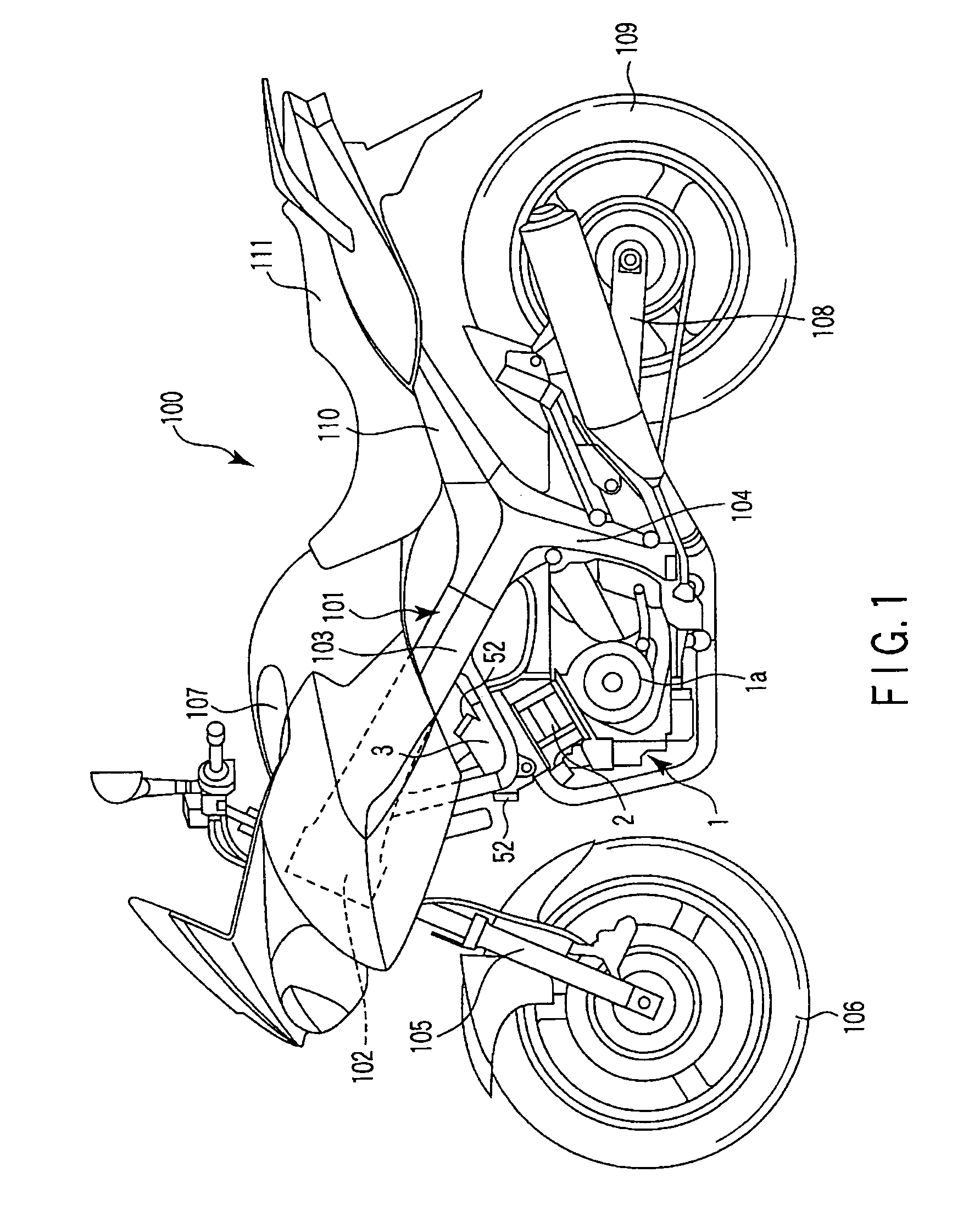
[0040]FIG. 1 shows a motorcycle 100 according to a preferred embodiment of the invention. The motorcycle 100 preferably includes a frame 101. The frame 101 includes a head pipe 102, left and right main frames 103 (only one of them being shown), and left and right rear-arm brackets 104 (only one of them being shown).

[0041]The head pipe 102 is positioned at a front end of the frame 101 to support a front wheel 106 through a front fork 105. The main frames 103 extend rearwardly of the head pipe 102 and incline downward as they extend rearwardly of the head pipe 102. The main frames 103 support a fuel tank 107.

[0042]The rear-arm brackets 104 project downward from rear ends of the main frames 103. The rear-arm brackets 104 pivotally support a rear arm 108. The rear arm 108 extends rearwardly of the rear-arm brackets 104. A rear wheel 109 is supported at a rear end of the rear arm 1...


PUM


Abstract

A valve gear includes a camshaft having valve gear cams, first and second rocker shafts, a first rocker arm supported on the first rocker shaft, and a second rocker arm supported on the second rocker shaft: The valve gear cams, respectively, include a cam nose projecting from a base circle, and the first rocker shaft supporting the first rocker arm is positioned forwardly of a center line, which passes through a center of the camshaft to extend axially of a cylinder, in a direction of rotation of the camshaft:. The first rocker shaft is shifted closer to the camshaft than a center of rotation of a roller bearing is, when the roller bearing won the first rocker arm contacts with the base circle of the valve gear cam.

Description

[0001]This Application is a National Stage application under U.S.C. § 371 based on International Application No. PCT / JP2004 / 010879 filed on Jul. 23, 2004, and further claims priority under 35 U.S.C. § 119 of Japanese Application No. 2003-207668, filed on Aug. 18, 2003.BACKGROUND OF THE INVENTION[0002]1. Field of the Invention[0003]The present invention relates to a valve gear including rocker arms having roller bearings at contact portions thereof with valve gear cams, and an overhead cam type four-cycle engine having such a valve gear. Further, the present invention relates to a vehicle such as a motorcycle including a four-cycle engine and such a valve gear.[0004]2. Description of the Related Art[0005]So-called SOHC (Single Overhead Camshaft) type four-cycle engines are known and include a single camshaft that drives exhaust valves and intake valves. This type of four-cycle engine includes an exhaust rocker arm, which transmits movements of an exhaust cam to exhaust valves, and an...

Claims


Application Information

Patent Timeline
IPC IPC(8): F01L1/18F01L1/053F01L1/08F01L1/26F01M9/10
CPCF01L1/022F01L1/182F01L1/26F01L1/053Y10T74/2107F01L2001/0535F01L2105/00F01M9/101F01L2305/00
Inventor SAKURAI, MOTOKI
Owner YAMAHA MOTOR CO LTD
Why Eureka
Eureka Blog
Learn More