
Method of directional filtering for post-processing compressed video

a directional filtering and compressed video technology, applied in the field of post-processing compressed digital images, can solve the problems of limiting the usefulness of real-time video applications, staircase noise of compressed images, and all of these artifacts can be annoying to viewers of images, so as to reduce the impact of edge sharpness, avoid image complications, and save computational resources

Inactive Publication Date: 2007-04-10
SHARP KK
View PDF41 Cites 88 Cited by
  • Summary
  • Abstract
  • Description
  • Claims
  • Application Information

AI Technical Summary

Benefits of technology

The present invention provides a method for improving the quality of decompressed images by selectively filtering pixels in a way that preserves edge sharpness and reduces computational resources. The filtering is done by establishing a filtering axis parallel to an image edge in a block of pixels and selectively filtering a plurality of pixels arrayed parallel to the filtering axis. The method can also be applied separately to interlaced video fields to avoid image complications arising from separate processing. Overall, the invention provides a more efficient and effective way to improve the quality of decompressed images.

Problems solved by technology

This is a particular problem in areas of uniform color and along color boundaries.
In addition, the decompressed image may exhibit “staircase noise,” a term which is descriptive of an appearance of an edge in the image.
All of these artifacts can be annoying to viewers of the image.
Generally, these methods are complex and often iterative limiting their usefulness in real time video applications.
While filtering pixel segments normal to block boundaries is useful in addressing the blocking effect, it does not necessarily address ringing artifacts.
Further, edges may be filtered and some portions of diagonal edges may be filtered repeatedly, adversely impacting the sharpness of the decompressed image.

Method used


Image

  • Method of directional filtering for post-processing compressed video
  • Method of directional filtering for post-processing compressed video
  • Method of directional filtering for post-processing compressed video

Examples


Embodiment Construction

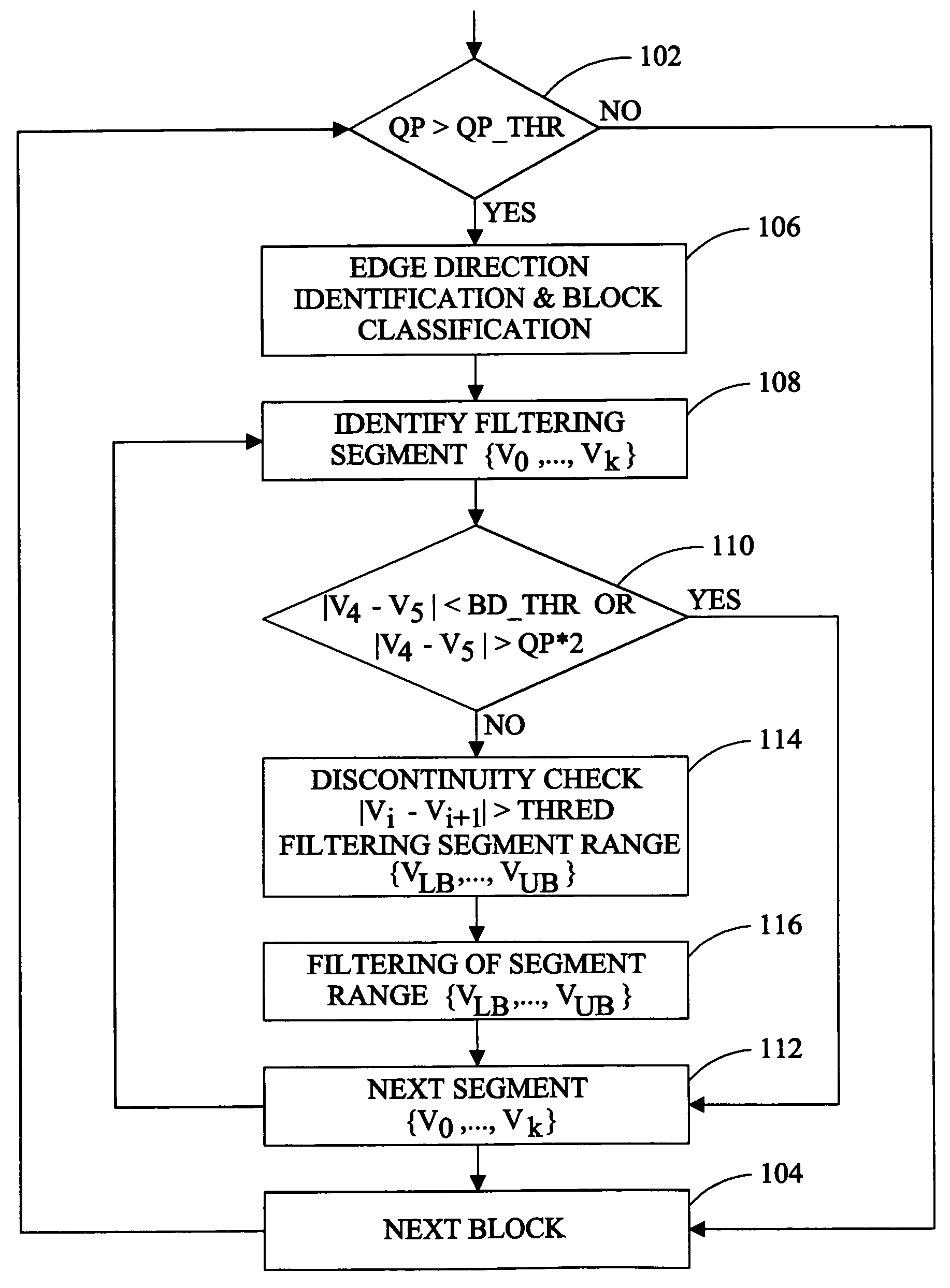
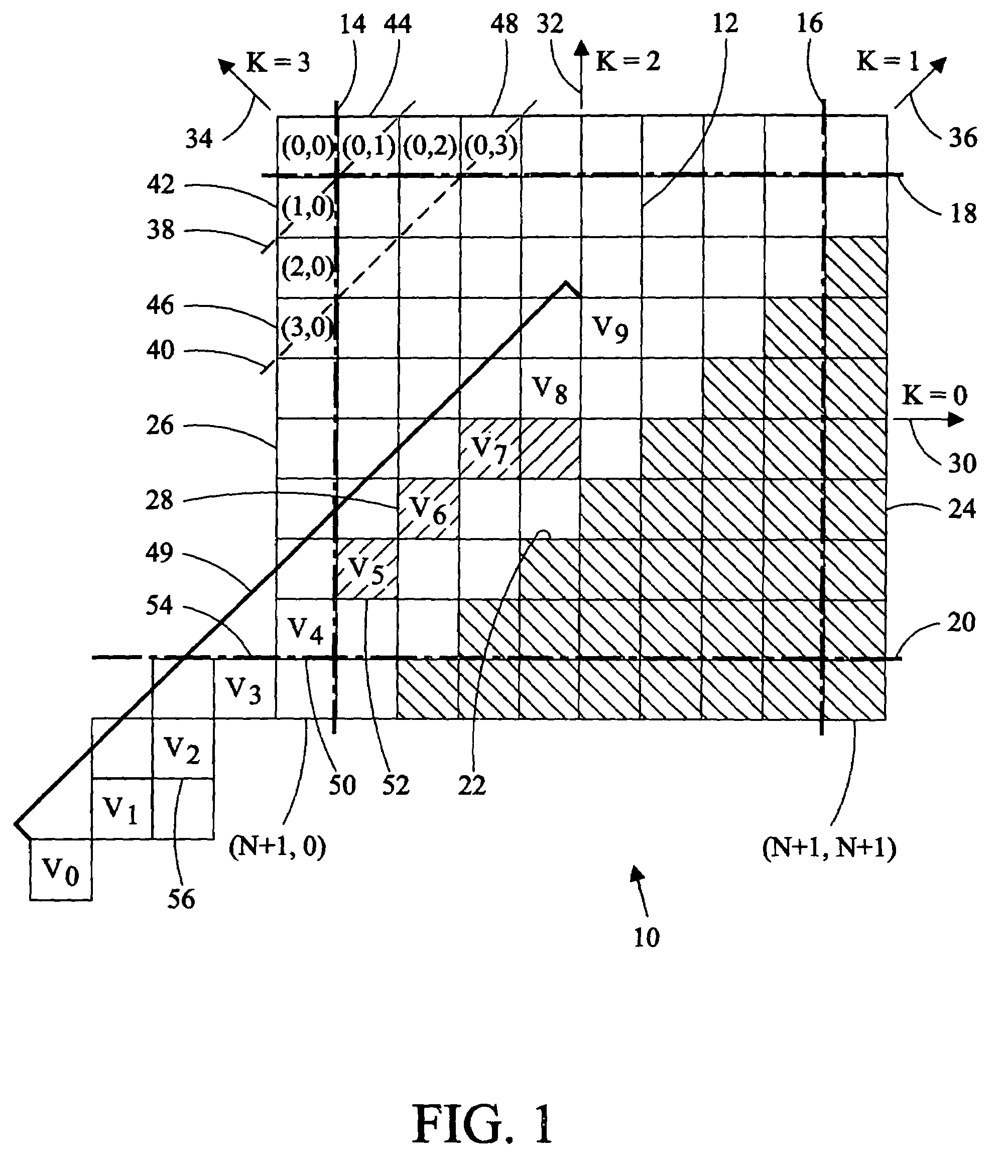
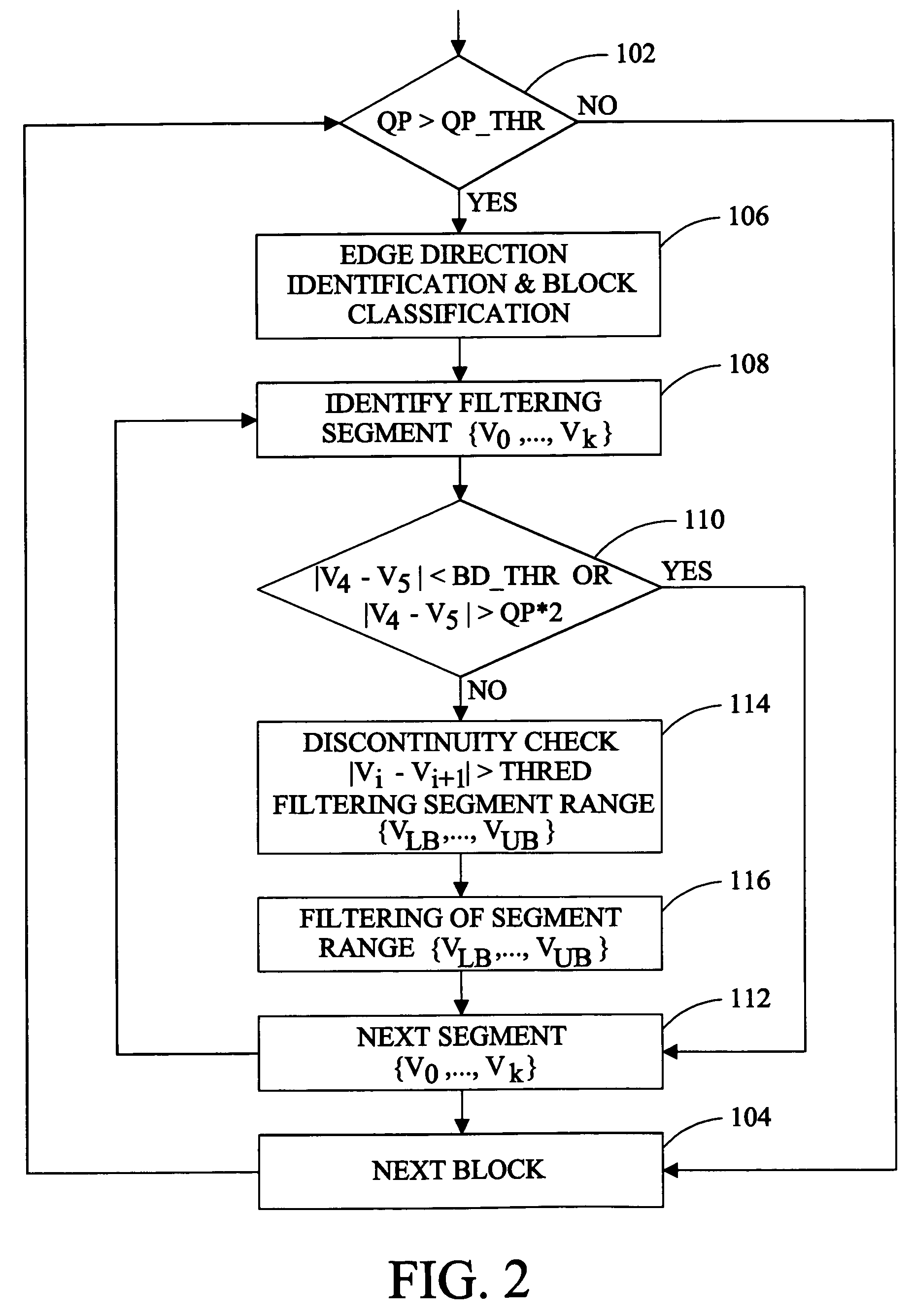
[0011]In the transform coding process an N (pixel)×N (pixel) image is subdivided into n×n sub-images or blocks and the transform is applied to the individual pixels on a block by block basis. For example, in the Discrete Cosine Transform (DCT) compression process utilized by in the JPEG (ISO 10918) and MPEG-2 (ISO / IEC 13818) image compression processes the image is subdivided into 8×8 blocks for coding. FIG. 1 illustrates a portion of a larger image 10 that has been subdivided into blocks, such as the block 12 that is bounded by the block boundaries 14, 16, 18, and 20. Pixels outside of the area bounded by the block boundaries are pixels included in adjacent blocks. An image edge 22, formed by the boundaries of pixels of a first 24 and second 26 color divides the block 12 diagonally. It is understood that a block of pixels, as used herein, may be any plurality of pixels defining any pattern.

[0012]Decompressed images may exhibit several artifacts of the compression-decompression proc...


PUM


Abstract

A method of post-processing decompressed images includes identification of the direction of an image edge in a pixel block of the image and filtering applied along the boundary of the block in a direction substantially parallel to the detected image edge. Pixels are selected for filtering on the basis of the quantization parameter of the block of which they are members, the relative difference between pixels adjacent to the block boundary, and significant changes value of pixels in a filtering segment. Filtering is applied parallel to the detected edge to protect the sharpness of the edge while reducing or eliminating blocking and ringing artifacts. A method of separately post-processing fields of interlaced video eliminating complications arising from separate compression of the fields is also disclosed.

Description

BACKGROUND OF THE INVENTION[0001]The present invention relates to post-processing of decompressed digital images and, more particularly, to a method of directional, selective filtering of decompressed images.[0002]Transform coding is a common method for compressing digital images. For examples, transform coding is featured in the JPEG (ISO 10918) standard related to still images and the MPEG-2 (ISO / IEC 13818) standard related to motion video. Generally, transform coding involves subdividing an image into smaller blocks or groups of pixels, applying a “reversible transform” (such as the Discrete Cosine Transform (DCT)) to the pixels of the blocks, quantizing the frequency coefficients produced by the transform, and coding of the results. While transform coding can achieve a high compression ratio, information in the original image is discarded in the compression-decompression process degrading the decompressed image, especially in video sequences with considerable motion.[0003]Decomp...

Claims


Application Information

Patent Timeline
Patent Type & Authority Patents(United States)
IPC IPC(8): H04B1/66G06T5/00G06T5/10G06T5/20H04N1/409H04N1/41H04N5/14H04N7/26H04N7/30
CPCG06T5/002H04N19/176H04N19/86H04N19/14H04N19/80H04N19/117G06T2207/20192G06T5/70
Inventor ZENG, WENJUN
Owner SHARP KK
Learn More