
Methods and devices for forming a high-power coherent light beam

a light beam and coherent technology, applied in semiconductor lasers, laser details, instruments, etc., can solve the problems of limited number of diodes that may be used in the same light source, limited the number of diodes that can be coupled together with purely passive elements, and limited the number of diodes that can be used in parallel, so as to and reduce the variation in phas

Active Publication Date: 2007-04-10
THE BOEING CO
View PDF7 Cites 18 Cited by
  • Summary
  • Abstract
  • Description
  • Claims
  • Application Information

AI Technical Summary

Benefits of technology

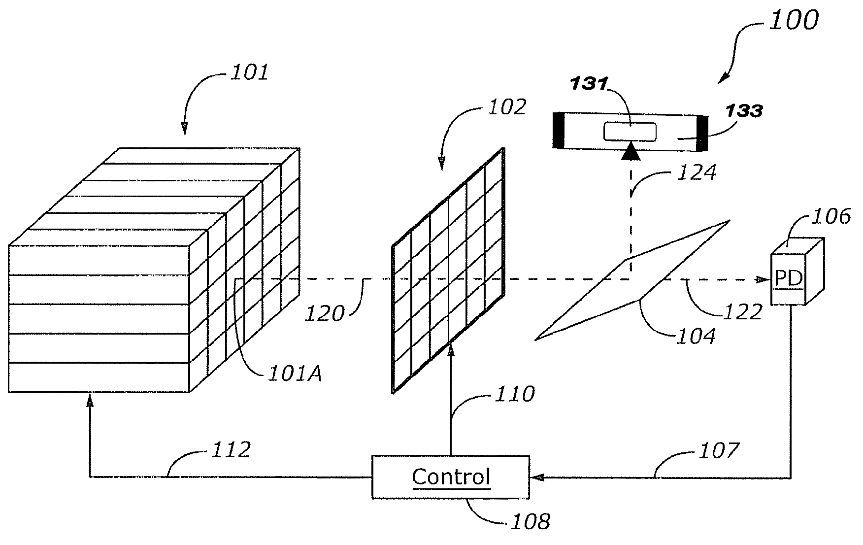
The patent describes a technique for producing a high-energy coherent light beam using a diode laser with an array of laser diodes. The laser beams are directed to a spatial light modulator with an array of pixels, and the phase variation across the beam wavefront is monitored. A feedback signal is provided to control electronics, which process the feedback signal to modulate a local index of refraction within one or more pixels of the SLM to reduce the variation in phase across the beam wavefront. This technique allows for relatively large diode arrays to be formulated. The technical effect of this patent is to provide a more efficient and effective way to produce high-power light beams with reduced phase variations.

Problems solved by technology

While diode lasers are generally highly efficient and robust, their usefulness in many applications is limited by the relatively low power of the beam produced.
While this technique has been employed with some success, the number of diodes that can be coupled together with purely passive elements has been limited in practice by phase differences in light produced by the multiple sources.
That is, variations in phase across the wavefront of the resultant beam have restricted the number of diodes that may be simultaneously used in the light source.
A tradeoff therefore exists between the power and the phase coherence of the beam, with increases in one resulting in decreases in the other.

Method used


Image

  • Methods and devices for forming a high-power coherent light beam
  • Methods and devices for forming a high-power coherent light beam
  • Methods and devices for forming a high-power coherent light beam

Examples


Embodiment Construction

[0015]The following detailed description of the invention is merely exemplary in nature and is not intended to limit the invention or the application and uses of the invention. Furthermore, there is no intention to be bound by any theory presented in the preceding background of the invention or the following detailed description of the invention.

[0016]According to various exemplary embodiments, a high power diode laser suitable for laser and other applications is formed from an array of laser diodes or similar sources of light. Light produced by each of the diode sources passes through a spatial light modulator, which adjusts the phase of the light on a localized basis. That is, each pixel of the spatial light modulator suitably adjusts the phase of light passing through that pixel without significantly affecting the phase of light passing through other pixels. By controlling the localized phase of the light across the wavefront of the beam, phase differences can be significantly re...


PUM


Abstract

A diode laser for providing a high-energy coherent light beam suitably includes an array of laser diodes, each producing a laser beamlet. The beamlets are provided to a spatial light modulator (SLM) with an array of pixels, each pixel corresponding to a portion of the light beam. The phase variation across the light beam wavefront is monitored at a detector, and a feedback signal indicative of the phase variation is provided to control electronics. The control electronics process the feedback signal to modulate a local index of refraction within one or more pixels of the SLM to reduce the variation in phase across the beam wavefront. Because phase variations across the beam wavefront are reduced, relatively large diode arrays can be formulated, thereby resulting in relatively high powered diode lasers.

Description

TECHNICAL FIELD[0001]The present invention generally relates to diode lasers, and more particularly relates to devices and techniques for producing a high-power coherent light beam in a diode laser.BACKGROUND[0002]The use of laser-generated electromagnetic optical energy has become ubiquitous in applications ranging in areas from commercial to national defense. An illustrative example of the former is the use of optical energy for industrial materials processing, including cutting, welding and surface treatment. End products resulting from such implementations come from such wide ranging business areas as automotive, aerospace, appliance and shipbuilding. More exotic applications can include rock drilling for mining and / or oil and gas exploration purposes. Directed energy or so-called “laser weapons” are finding increased acceptance in the defense community because of the position-sensitive lethality delivery. As lasers become smaller, more efficient and robust, it becomes easier to...

Claims


Application Information

Patent Timeline
Patent Type & Authority Patents(United States)
IPC IPC(8): H01S3/10H01S3/13G02B26/06H01S5/068H01S5/40
CPCG02B27/0087H01S5/4025G02F2203/18H01S5/06821
Inventor SOX, DANIEL J.HUNT, JEFFREY H.
Owner THE BOEING CO
Learn More