
Wireless communication device with integrated battery/antenna system

a communication device and battery technology, applied in the direction of loop antennas, resonant antennas, radiating elements structural forms, etc., can solve the problem that devices are not able to send certain types of signals very far

Active Publication Date: 2007-04-10
GOOGLE TECHNOLOGY HOLDINGS LLC
View PDF11 Cites 91 Cited by
  • Summary
  • Abstract
  • Description
  • Claims
  • Application Information

AI Technical Summary

Benefits of technology

The present invention is about a wireless communication circuit arrangement that includes a battery, a temperature sensing element, and an electromagnetic wave radiating and receiving element. The temperature sensing element is thermally coupled to the battery and can measure the resistance of the temperature sensing device. The circuit arrangement also allows for the simultaneous communication of signals through the electromagnetic wave radiating and receiving element. An inductive element and a capacitive element are included to impede signals from passing through the temperature sensing element and the electromagnetic wave radiating element, respectively. The electromagnetic wave radiating and receiving element can be a loop antenna. The technical effect of this invention is to provide a reliable and efficient wireless communication circuit arrangement that can measure temperature and communicate signals simultaneously.

Problems solved by technology

That is to say, it is desirable that the device is not able to send certain types of signals very far.
However, these prior-art solutions require additional terminals to connect and energize the antenna element, thereby necessitating that the device hardware be redesigned.
Those that have been able to use existing terminals require a complicated multiplexing scheme where use of the terminal is shared by time switching so that only one signal is present at a given time.

Method used


Image

  • Wireless communication device with integrated battery/antenna system
  • Wireless communication device with integrated battery/antenna system
  • Wireless communication device with integrated battery/antenna system

Examples


Embodiment Construction

[0020]As required, detailed embodiments of the present invention are disclosed herein; however, it is to be understood that the disclosed embodiments are merely exemplary of the invention, which can be embodied in various forms as illustrated in the non-limiting exemplary embodiments of FIGS. 1–6. Therefore, specific structural and functional details disclosed herein are not to be interpreted as limiting, but merely as a basis for the claims and as a representative basis for teaching one skilled in the art to variously employ the present invention in virtually any appropriately detailed structure. Further, the terms and phrases used herein are not intended to be limiting; but rather, to provide an understandable description of the invention.

[0021]The terms “a” or “an”, as used herein, are defined as one or more than one. The term plurality, as used herein, is defined as two or more than two. The term another, as used herein, is defined as at least a second or more. The terms includi...


PUM


Abstract

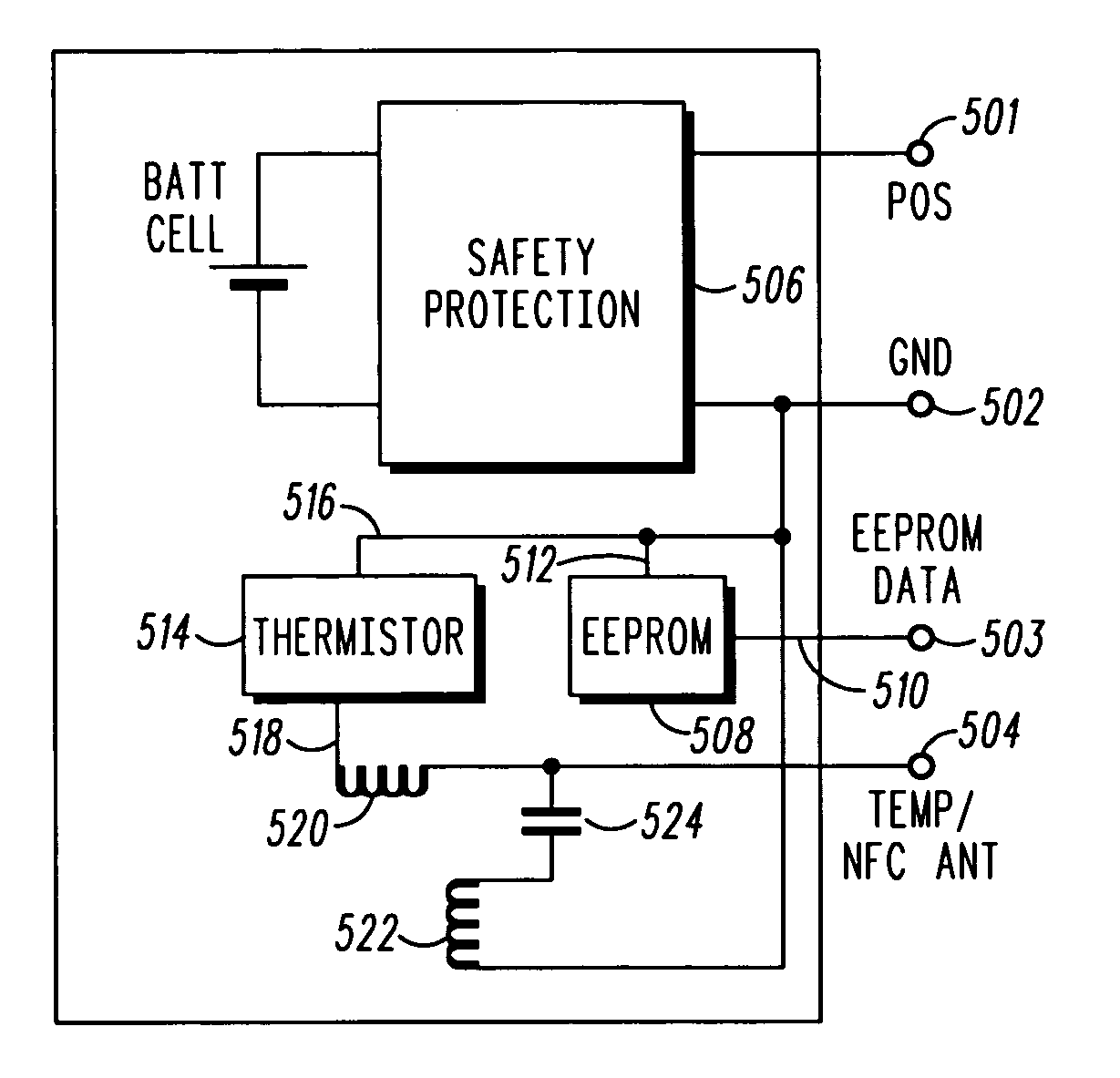
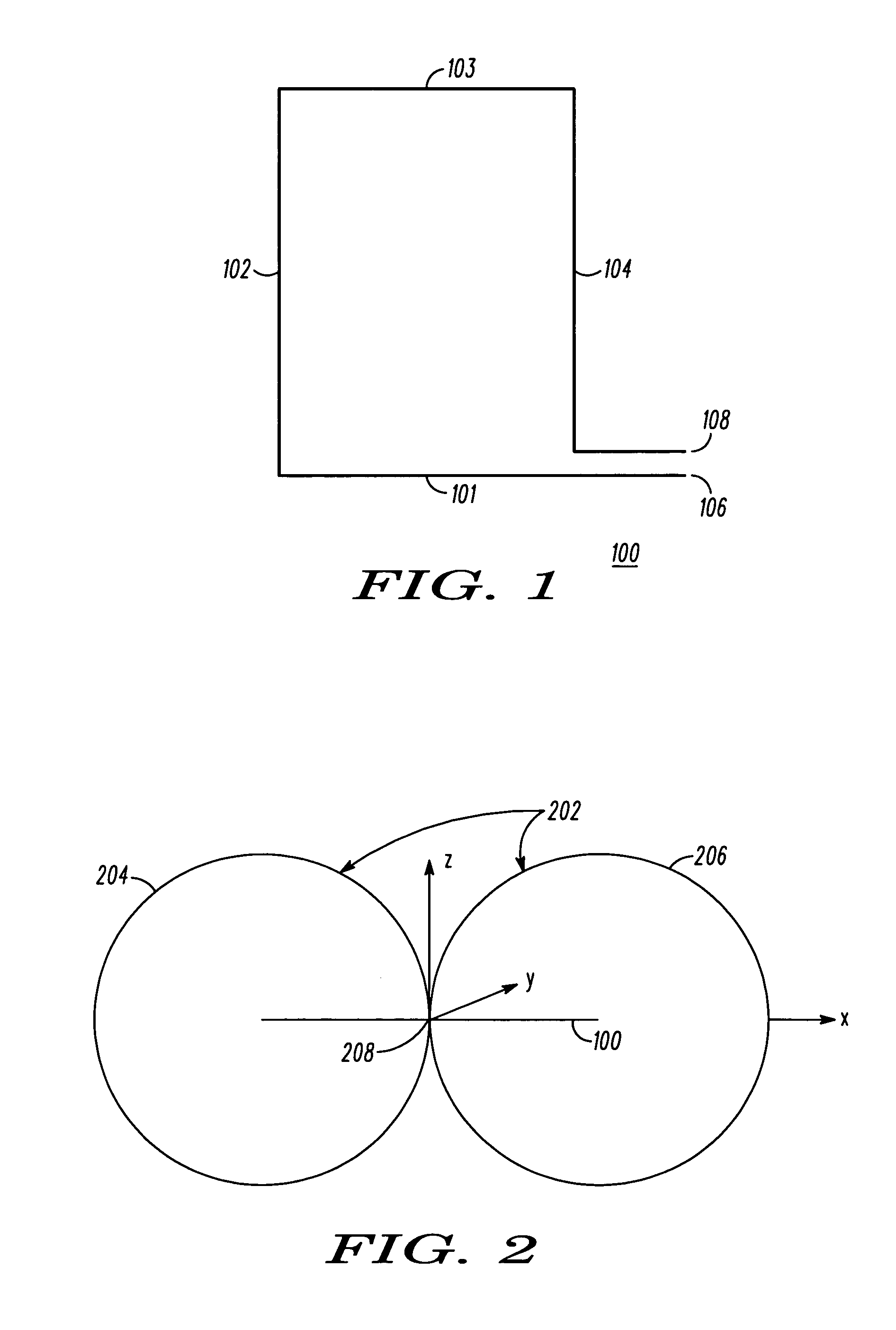
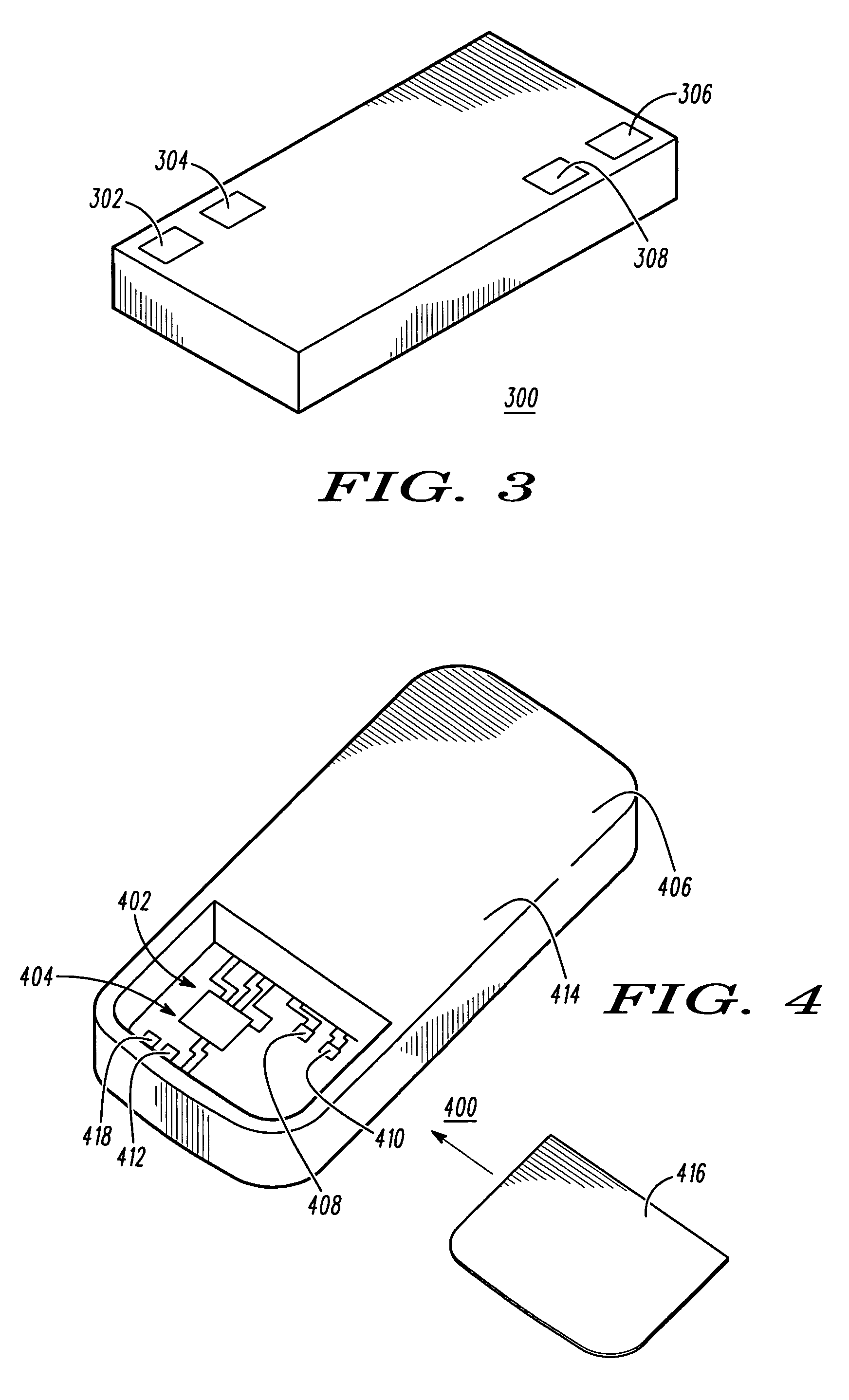
A loop antenna (100) shares terminals with a thermistor on a battery. The battery (300) has at least two terminals (302&304) that connect to a thermistor (514). An electromagnetic wave radiating and receiving element (522) shares the at least two terminals (302&304) with the thermistor (514) but is electrically isolated from the thermistor (514) so that the thermistor (514) resistance can be measured while the electromagnetic wave radiating and receiving element (522) can communicate electrical RF signals via the at least two terminals with an RF circuit. A wireless communication device that uses the battery (300) and the loop antenna (100) is also disclosed.

Description

CROSS-REFERENCE TO RELATED APPLICATION[0001]The present patent application is related to co-pending and commonly owned U.S. patent application Ser. No. 11 / 227,367, entitled “WIRELESS COMMUNICATION DEVICE WITH INTEGRATED ANTENNA,” filed on even date with the present patent application, the entire teachings of which being hereby incorporated by reference.FIELD OF THE INVENTION[0002]The present invention generally relates to the field of radio frequency antennas and more particularly to integrated near-field antennas.BACKGROUND OF THE INVENTION[0003]The progression of features and performance of portable wireless communications devices, such as cellular telephones, PDAs and the like, has occurred at an almost exponential rate since the devices were first introduced into the consumer market. Manufacturers are constantly working to reduce the size, extend battery life, and increase communication reliability and range. In addition, the devices now commonly have features such as picture, v...

Claims


Application Information

Patent Timeline
Patent Type & Authority Patents(United States)
IPC IPC(8): H01Q1/24
CPCH01Q1/243H01Q1/44
Inventor LEIZEROVICH, GUSTAVO D.BURNETTE, DONALD W.CASTANEDA, JULIO C.GOMEZ, ORLANDO
Owner GOOGLE TECHNOLOGY HOLDINGS LLC
Learn More