
Flow control system and method

a flow control and flow control technology, applied in data switching networks, frequency-division multiplexes, instruments, etc., can solve problems such as congestion, packet loss, and rtp has no congestion avoiding function,

Active Publication Date: 2007-04-03
NEC CORP
View PDF22 Cites 34 Cited by
  • Summary
  • Abstract
  • Description
  • Claims
  • Application Information

AI Technical Summary

Benefits of technology

[0014]It is an object of the present invention to provide a flow control system and method which simultaneously achieve congestion avoidance and continuous reconstruction.

Problems solved by technology

However, RTP has no congestion avoiding function.
For this reason, if data in an amount beyond the network capacity is to be transmitted, congestion occurs, and packet loss often happens.
While congestion is continuing, voice is interrupted, and an image becomes inaccurate.
In addition, data transfer using TCP cannot be executed.
However, if congestion continues due to RTP, data that can be transmitted by TCP is exponentially decreased (repeatedly halved) and becomes almost zero.
However, in streaming, reconstruction is sometimes interrupted, resulting in a large degradation in quality (i.e., a time factor is important).
That is, in streaming, not only avoiding congestion is necessary but also transmission must be executed while maintaining an expected time continuity (otherwise, reconstruction is stopped halfway, resulting in adverse influence on the quality).
Generally, stream data cannot be simply switched halfway.
However, an IP network itself does not have this function.
However, in the window control scheme, since a congestion window is controlled, the transmission bit rate is not directly defined.
In addition, the delay time in the network, which changes for each packet, directly leads to a variation in transmission bit rate.
However, since switching points are present only at a predetermined time interval, continuous reconstruction is not always guaranteed.
This problem that reconstruction stops halfway is posed even when an encoding means capable of encoding data in real time is used as an application.
However, although the probability of continuous reconstruction can be increased, halfway reconstruction stop cannot be completely eliminated.
It is difficult to execute a dialogue-type application such as a video phone.

Method used


Image

  • Flow control system and method
  • Flow control system and method
  • Flow control system and method

Examples


Embodiment Construction

[0020]The present invention will be described below in detail with reference to the accompanying drawings.

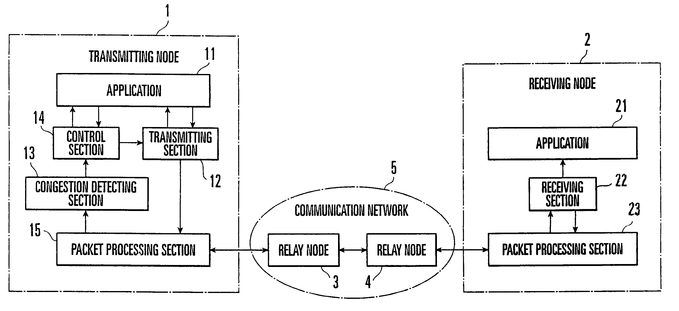
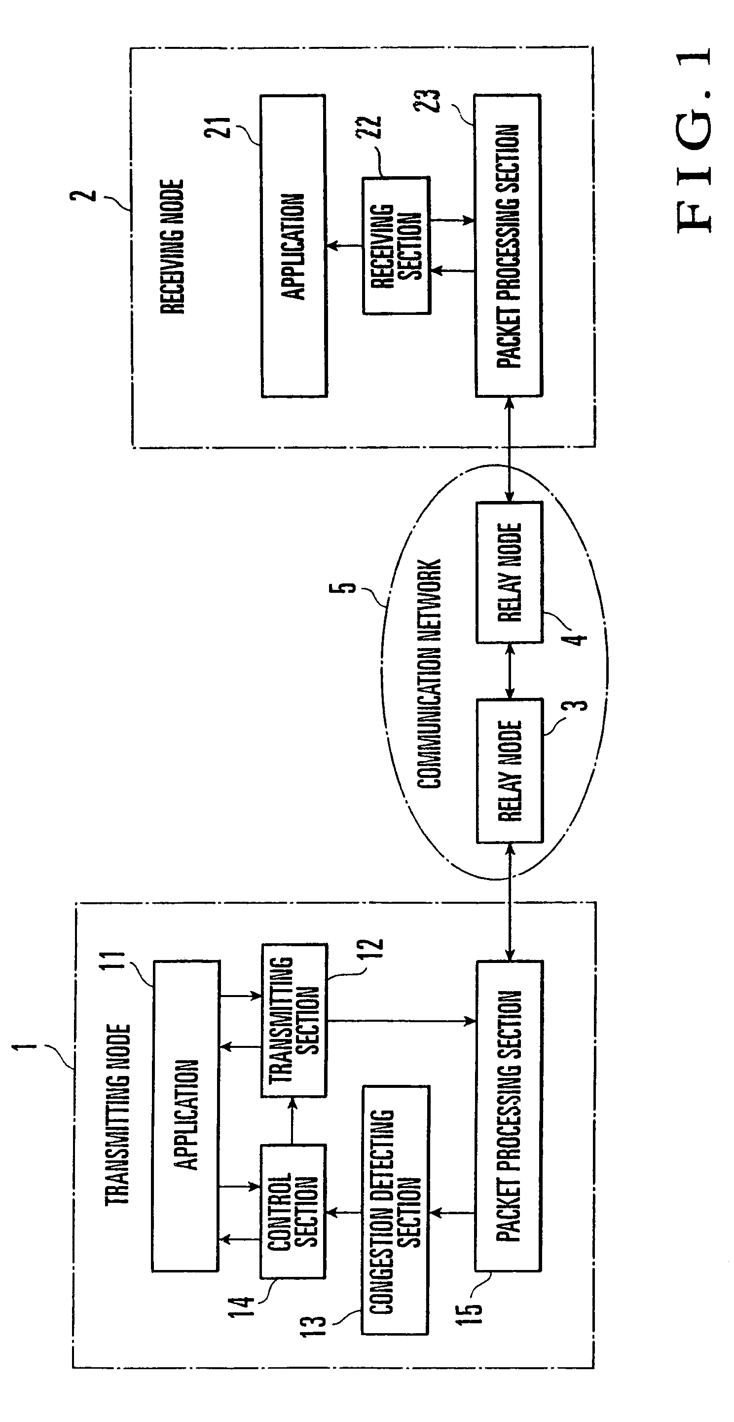
[0021]FIG. 1 shows a stream data transmission system according to the first embodiment of the present invention. Referring to FIG. 1, a transmitting node 1 and receiving node 2 are connected through a communication network 5 formed from a plurality of relay nodes 3 and 4. Stream data is transmitted from the transmitting node 1 to the receiving node 2.

[0022]The transmitting node 1 comprises an application 11 which generates stream data to be transmitted, a transmitting section 12 which forms packets of the stream data generated by the application 11 at a transmission packet rate designated by a control section 14 and transmits the data packets, a congestion detecting section 13 which detects congestion which has occurred in the communication network 5 that connects the transmitting node 1 and receiving node 2, the control section 14 which controls the transmission packet rate of ...


PUM


Abstract

A flow control system include a congestion detecting section and control section. The congestion detecting section detects congestion in a packet switching network. The control section is arranged in a transmitting node. When the congestion detecting section detects congestion, the control section calculates a new transmission packet rate. When the new transmission packet rate is smaller than a current transmission packet rate, the control section changes the current transmission packet rate to the new transmission packet rate after transmission of data to be transmitted to a receiving node. A flow control method is also disclosed.

Description

BACKGROUND OF THE INVENTION[0001]The present invention relates to a flow control system and method for avoiding any congestion at a node connected to a packet switching network to execute communication protocol processing.[0002]Currently, packet switching networks (IP networks) using the Internet protocol (IP) are widely used. In an IP network, end-to-end congestion is avoided between transmitting and receiving nodes. That is, in protocol layer 4 serving as the transport layer of the reference model of OSI (Open Systems Interconnection), congestion is avoided by flow control of TCP (Transmission Control Protocol). TCP is a connection-oriented transfer protocol which transfers data on the basis of a virtual circuit (VC). In the flow control of TCP, a window control scheme is used. When a transmitting node detects packet loss in a network, the cause for it is determined as congestion, and the transmission data amount (congestion window) is reduced to ½. A congestion window is an estim...

Claims


Application Information

Patent Timeline
IPC IPC(8): G06F15/16H04L47/2416
CPCH04L47/10H04L47/11H04L47/22
Inventor SENDA, YUZO
Owner NEC CORP
Learn More