
Dual-edged DIMM to support memory expansion

a memory expansion and dual-edged dimm technology, applied in the computer field, can solve the problems of a limited number of memory sockets, a small density server, and a large number of users demanding much more memory capacity

Inactive Publication Date: 2007-04-03
INT BUSINESS MASCH CORP
View PDF7 Cites 59 Cited by
  • Summary
  • Abstract
  • Description
  • Claims
  • Application Information

AI Technical Summary

Benefits of technology

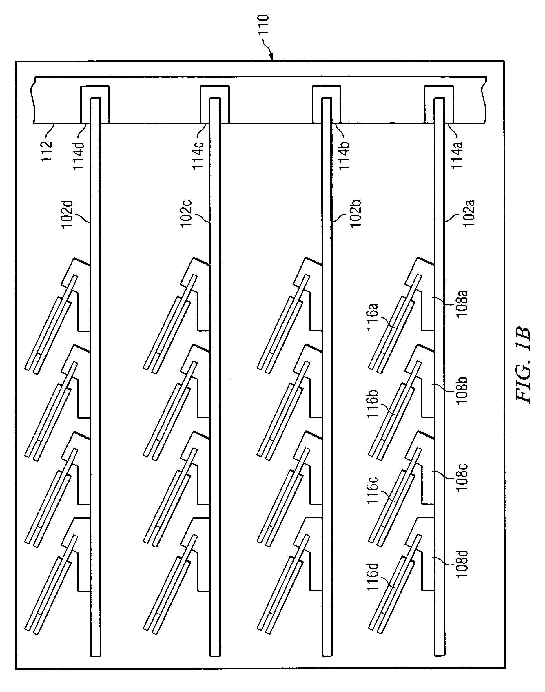
[0011]In response to the shortcomings of the prior art system described, the present invention is thus directed to a method and system for expanding the number of memory modules that can be coupled to a motherboard such as a server blade. A stack of multiple Dual In-line Memory Modules (DIMMs) is formed using novel double-connector-edge DIMMs, which each have connector pins on their opposite edges. Alternatively, the double-connector-edge DIMM is used to couple the motherboard to a memory expansion card that has multiple single-edge pinned DIMMs coupled in a “daisy-chain.” In another embodiment, a Dual Inline Buffer Module (DIBM), which has a buffer for redrive but no DRAMs, coupled the motherboard to the memory expansion card.

Problems solved by technology

Therefore, to utilize all of this computing power, users are demanding much more memory capacity.
Some high density servers are so small that they can support only a limited number of memory sockets.

Method used


Image

  • Dual-edged DIMM to support memory expansion
  • Dual-edged DIMM to support memory expansion
  • Dual-edged DIMM to support memory expansion

Examples


Embodiment Construction

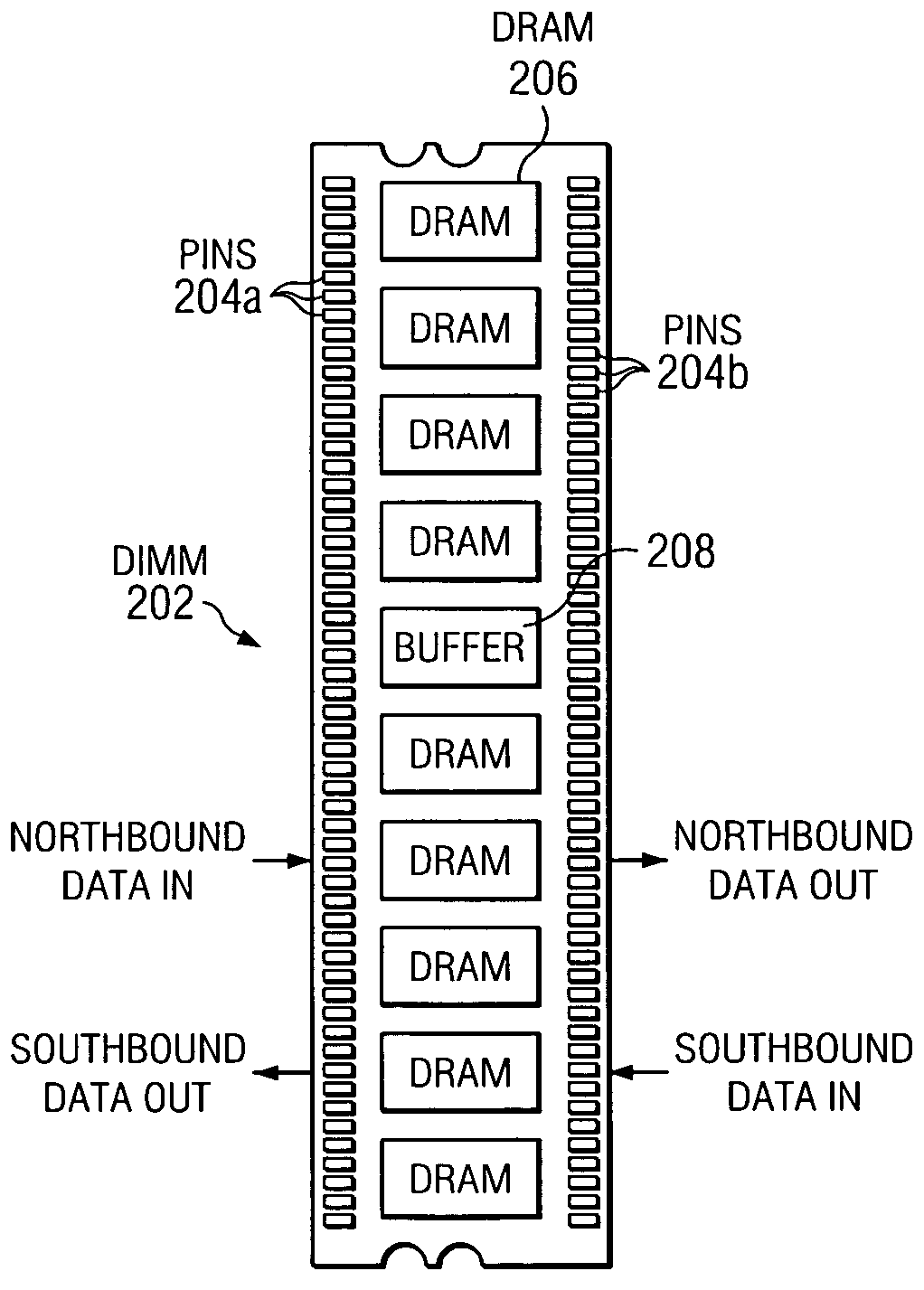
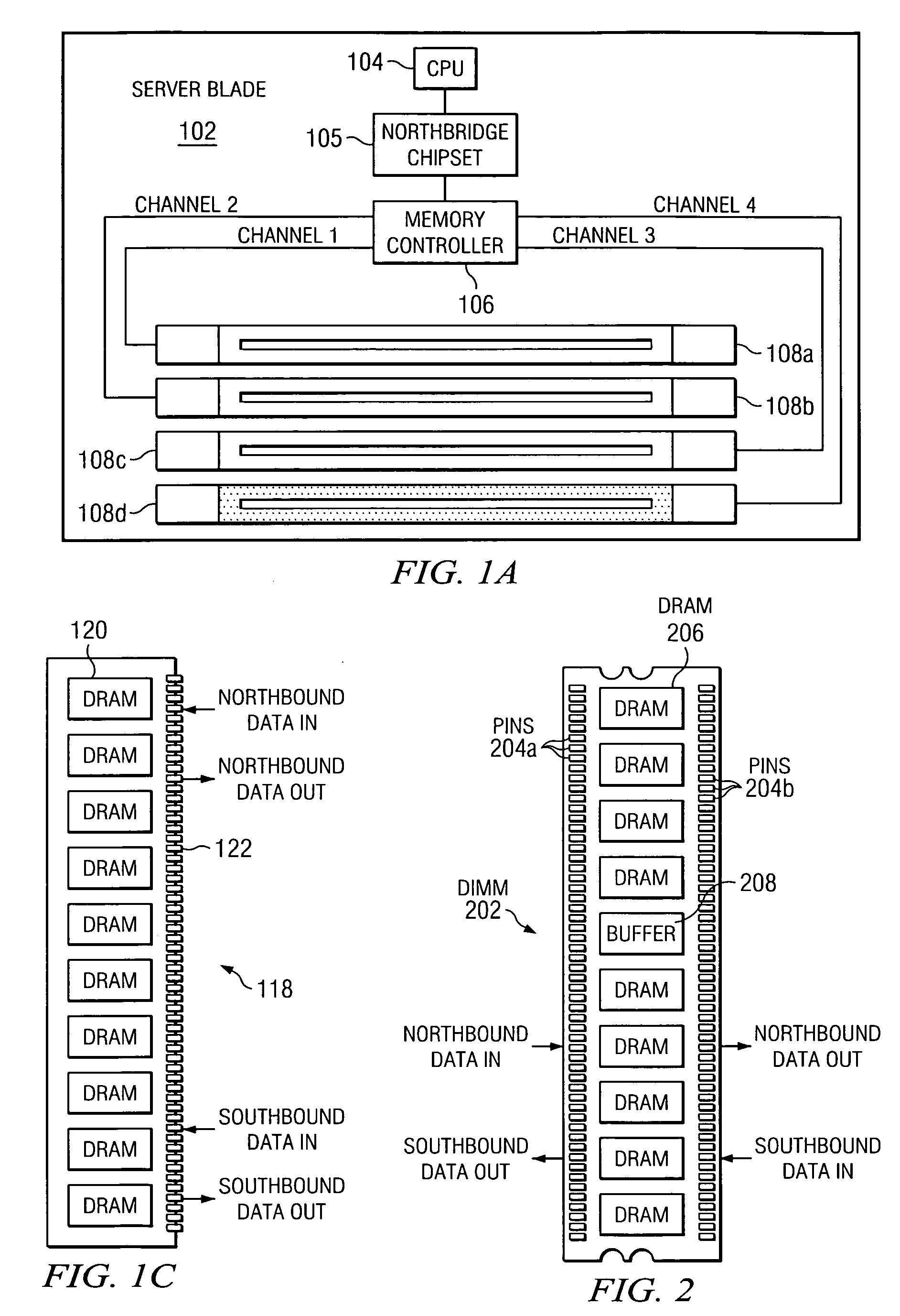
[0022]With reference now to the FIG. 2, there is depicted an inventive double-connector-edge Dual In-line Memory Module (DIMM) 202. On opposite edges of double-connector-edge DIMM 202 are pins 204a and 204b. Preferably, pins 204a and 204b each number 240 pins, in order to conform to the standard number of pins in a Low Profile (LP) DIMM (having a height of 1.2″) and a Very Low Profile (VLP) DIMM (having a height of 0.72″). Pins 204 provide electrical inputs for data and related signals as well as power and ground connections. As shown, double-connector-edge DIMM 202 has multiple Dynamic Random Access Memories (DRAMs) 206 for storing data.

[0023]In addition, double-connector-edge DIMM 202 has a buffer 208. Buffer 208, as the name implies, is a buffer for all data (including but not limited to data to be stored; data addresses; control signals such as Row Address Strobe (RAS) and Column Address Strobe (CAS), write enable, read enable, chip select, clock input, Error Correction Code—ECC...


PUM


Abstract

A method and system for expanding the number of memory modules that can be coupled to a motherboard such as a server blade is presented. A stack of multiple Dual In-line Memory Modules (DIMMs) is formed using novel double-connector-edge DIMMs, which each have connector pins on their opposite edges. Alternatively, the double-connector-edge DIMM is used to couple the motherboard to a memory expansion card that has multiple single-edge pinned DIMMs coupled in a “daisy-chain.”

Description

BACKGROUND OF THE INVENTION[0001]1. Technical Field[0002]The present invention relates in general to the field of computers, and in particular to memory devices. Still more particularly, the present invention relates to a method and system for expanding memory using a novel memory module that has connector pins on its opposite edges.[0003]2. Description of the Related Art[0004]Recent advances in high volume servers have introduced 64-bit processors and operating systems. These systems are capable of directly addressing vast amounts of memory. Therefore, to utilize all of this computing power, users are demanding much more memory capacity.[0005]Some high density servers are so small that they can support only a limited number of memory sockets. For example, consider a server blade 102 shown in FIG. 1a. Server blade 102 is populated with, inter alia, a Central Processing Unit (CPU) 104, which is often a cluster of multiple processors. Data is supplied to CPU 104 by a memory controller...

Claims


Application Information

Patent Timeline
Patent Type & Authority Patents(United States)
IPC IPC(8): G11C5/06
CPCG11C5/04
Inventor FOSTER, SR., JIMMY GRANT
Owner INT BUSINESS MASCH CORP
Learn More