
Disk drive self-servo writing using fundamental and higher harmonics of a printed reference pattern

a self-servo writing and reference pattern technology, applied in the direction of maintaining head carrier alignment, recording signal processing, instruments, etc., can solve the problems of rework or scrapping, complex and expensive servo writer, and high time-consuming servo-writing by the servo writer, so as to prolong the usable lifetime of printed media, improve the snr, and high track density

Inactive Publication Date: 2007-04-03
MAXTOR
View PDF4 Cites 53 Cited by
  • Summary
  • Abstract
  • Description
  • Claims
  • Application Information

AI Technical Summary

Benefits of technology

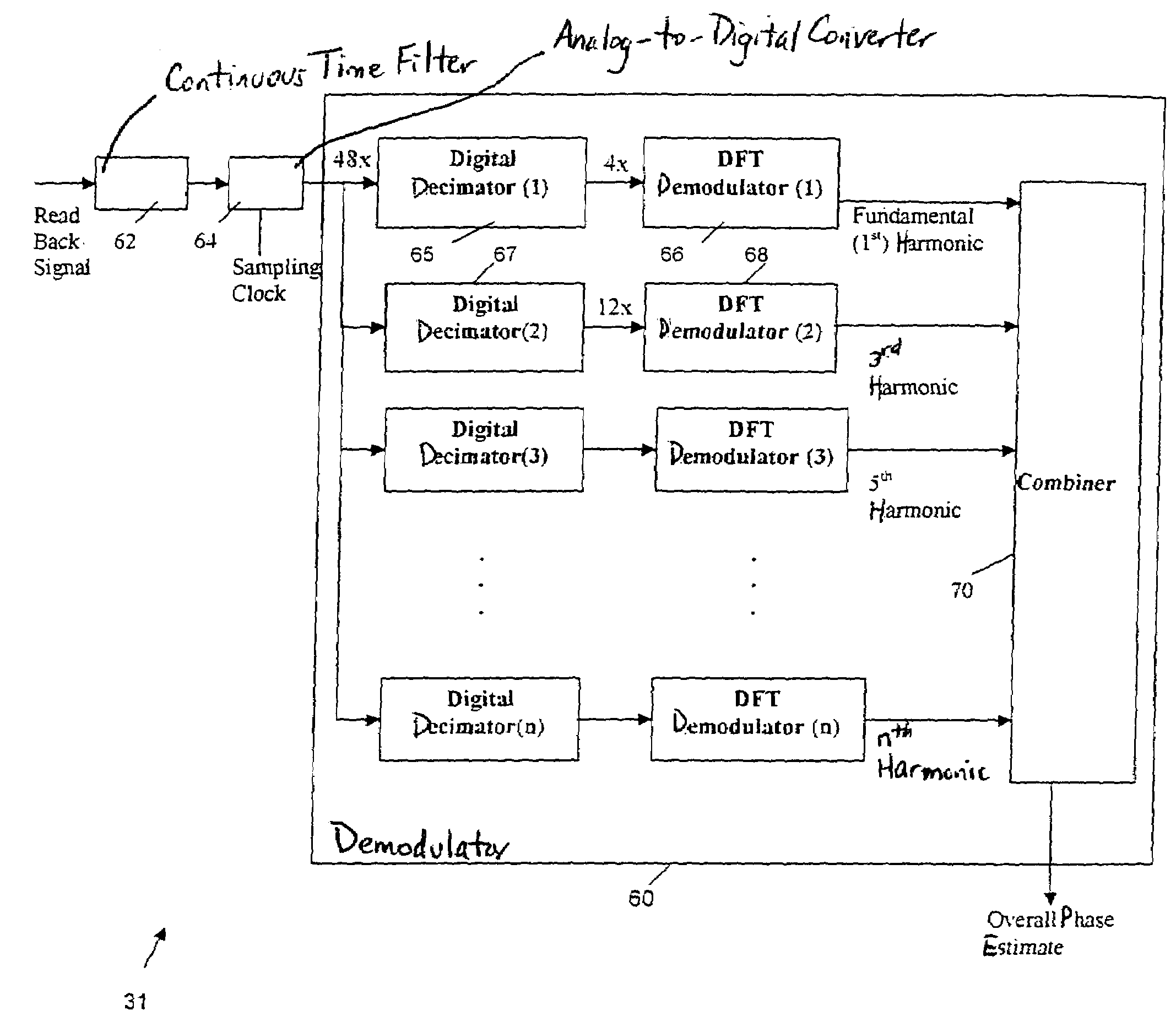
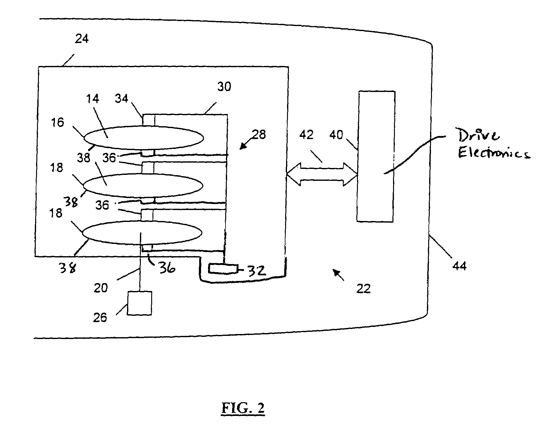
"The present invention provides a technique for demodulating a printed reference pattern that measures the fundamental and higher harmonics. This technique improves the signal-to-noise ratio (SNR) and allows for the use of higher track densities. Additionally, the invention provides a method for self-servo writing by transferring a reference pattern onto a disk and using the embedded servo information to precisely position and maintain the heads at concentric tracks. The invention also simplifies the assembly and testing process and eliminates the need for servo writers. The architecture of the disk drive read / write channel and controller allows for the extraction of embedded servo information for self-servo writing."

Problems solved by technology

If the drive fails the self-scan tests, it is either reworked or scrapped at this late manufacturing stage.
The servo writer is a complex and expensive machine, typically stabilized on a large granite base to minimize unwanted vibration, and employs laser interferometry for precise position measurements.
Further, servo-writing by the servo writer is very time consuming.
Thus, servo writing using servo writers in clean rooms requires both considerable is capital investment and severe time penalties attributable to servo writer bottlenecks.
Further, as track densities increase with evolving disk drive designs, servo writers have to be replaced or upgraded at considerable capital expense.
However, a disadvantage of this approach is that certain repeatable runout (RRO) information must be removed during the self-servo write operation.
Another disadvantage is that a servo writer is required to write the reference pattern on the reference disk.
While this method is satisfactory, challenges remain in generating and recording an accurate clock track on the disk surface.
Further, the time required to produce the spirals on the disk surface can be lengthy.
However, printed media signal-to-noise ratio (SNR) is marginal for existing disk drives due to the low pattern density available with current printing techniques.
One conventional approach to improving the SNR of printed media involves reducing the feature size in the printed media to increase the reference pattern density, but this is not practical due to limitations in optics and lithography.
Another approach is increasing the length of the reference pattern bursts (every doubling of burst length improves SNR by 3 dB) but the disk real estate available for more than one doubling is expensive.
In another approach, increasing the angle of the bursts leads to smaller feature sizes but this also leads to printing difficulties as the angle increases.
Yet another approach involves zoned printing by changing the reference pattern density at the disk ID and OD zones to improve the SNR but this leads to difficulties patching the reference patterns between the zones (particularly in the presence of eccentricity).
For printed media reference patterns, the limitations in spatial resolution of the printing process make it impractical to space transitions as closely as the servo patterns that are self-written with the disk drive heads.

Method used


Image

  • Disk drive self-servo writing using fundamental and higher harmonics of a printed reference pattern
  • Disk drive self-servo writing using fundamental and higher harmonics of a printed reference pattern
  • Disk drive self-servo writing using fundamental and higher harmonics of a printed reference pattern

Examples


Embodiment Construction

[0039]In one embodiment, the present invention provides self-servo writing servo patterns in a disk drive using a printed reference pattern. The printed reference pattern is printed on a reference disk by magnetic printing, and in one example includes magnetic segments having magnetic transitions wherein the direction of magnetization is generally along the circumferential direction of circular concentric disk tracks. Spatial separation between proximately printed segments is used to obtain phase information that provides timing and position information for positioning the heads over the tracks for self-servo writing of servo patterns without a servo writer.

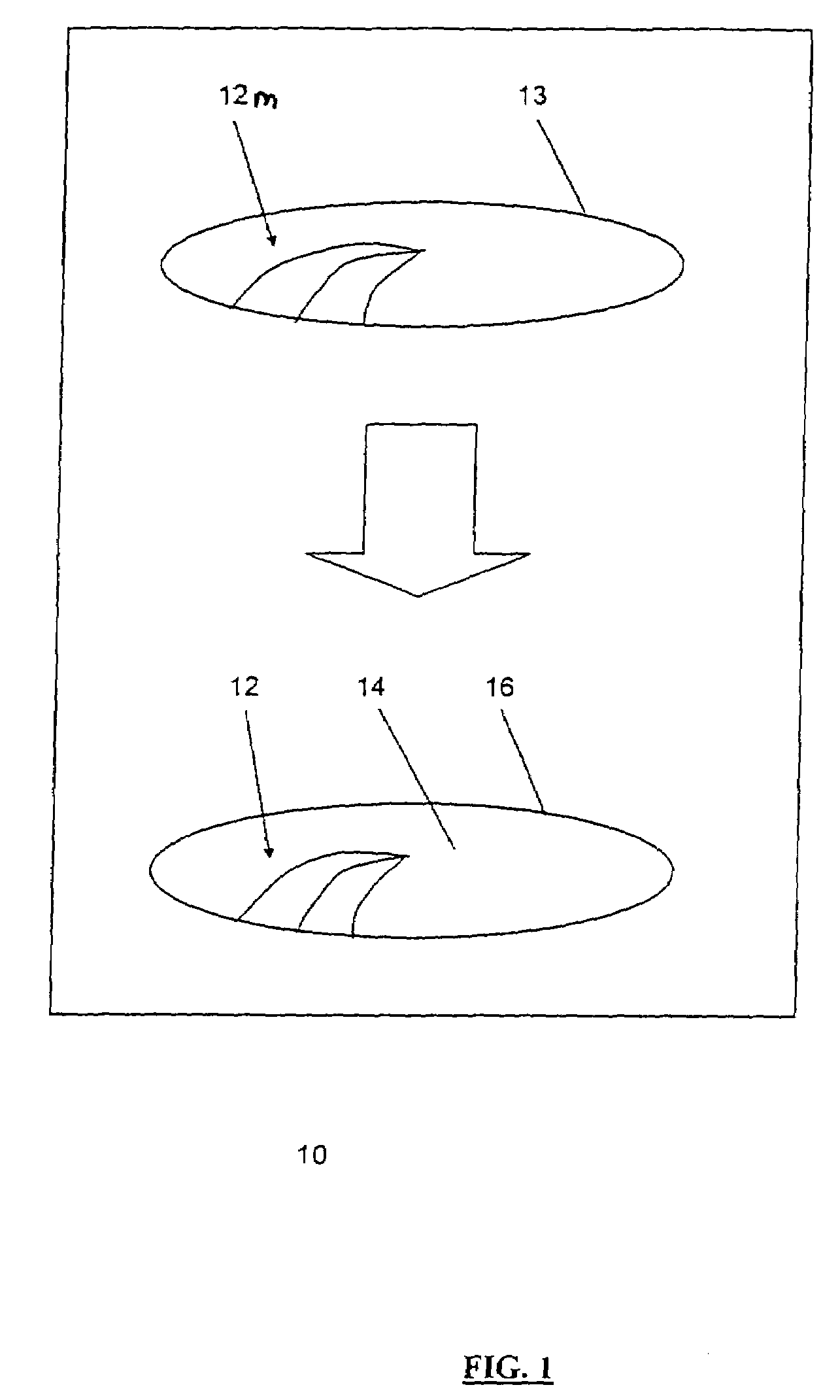
[0040]Referring to FIG. 1, a magnetic printing station 10 magnetically prints a mask reference pattern 12m from a mask 13 onto a disk surface 14 of a magnetic reference disk 16, as indicated by the block arrow, thereby forming a printed reference pattern 12 on the disk surface 14 of the reference disk 16. In this manner, the magn...


PUM

PropertyMeasurementUnit
diameteraaaaaaaaaa
dimensionaaaaaaaaaa
phaseaaaaaaaaaa

Abstract

Disk drive self-servo writing includes transferring a reference pattern by magnetic printing onto a reference disk, wherein the resulting printed reference pattern includes embedded servo information that provides servo timing and head position information, installing the reference disk and a head into the disk drive, reading the printed reference pattern using the head to generate a readback signal, sampling the readback signal at a sampling rate to generate a sampled signal, processing the sampled signal waveform spectrum to generate a recovered signal including the embedded servo information and fundamental and higher harmonics of the sampled signal, using the embedded servo information from the recovered signal to precisely position and maintain the head at concentric tracks of the reference disk, and self-writing servo patterns onto the tracks with the head.

Description

RELATED APPLICATION[0001]This application claims priority from U.S. Provisional Application No. 60 / 324,117, entitled “Demodulation Of Low Density Printed Media Bursts Using Information From Higher Harmonics”, filed on Sep. 21, 2001, which is incorporated herein by reference.FIELD OF THE INVENTION[0002]The present invention relates generally to writing servo patterns on a disk, and more particularly, to disk drive self-servo writing using a printed reference pattern on a disk.BACKGROUND OF THE INVENTION[0003]In many processing and computing systems, magnetic data storage devices such as disk drives are used for storing data. A typical disk drive includes a spindle motor for rotating one or more data storage disks having data storage surfaces, a head arm that supports one or more transducer heads, and an actuator for moving the heads radially across the disks to enable the heads to write data to and read data from concentric tracks on the disks.[0004]In general, the head is positioned...

Claims


Application Information

Patent Timeline
Patent Type & Authority Patents(United States)
IPC IPC(8): G11B5/00G11B20/10G11B5/02G11B5/09G11B21/02G11B5/596
CPCG11B5/59666G11B5/59688G11B27/19G11B5/59627
Inventor MOSER, MICHAEL ANTHONYPATAPOUTIAN, ARAMCEWEN, LEGAL REPRESENTATIVE, JOHNLIU, BINBUCH, BRUCEMCEWEN, DECEASED, PETER
Owner MAXTOR
Learn More