
System and method for monitoring and/or controlling attributes of multiple chemical mixtures with a single sensor

a technology of attributes and sensors, applied in chemical methods analysis, laboratory glassware, instruments, etc., can solve the problems of chemical process not meeting its goals, residues often remain on wafer surfaces, and chemical attacks on silicon surfaces

Inactive Publication Date: 2007-04-03
ADVANCED MICRO DEVICES INC
View PDF3 Cites 19 Cited by
  • Summary
  • Abstract
  • Description
  • Claims
  • Application Information

AI Technical Summary

Benefits of technology

The present monitoring system is a cost-effective and efficient way to monitor the attributes of multiple chemical mixtures in a semiconductor fabrication facility. The system uses a single sensor to measure the attributes of multiple chemicals simultaneously, reducing the need for separate sensors for each chemical. The sensor is a concentration sensor that can measure the concentration of chemicals in a sample flow. The system can also monitor the changes in attributes of a chemical mixture over time, allowing for better process characterization. The monitoring system is less expensive, requires less space, and can be used in a wider range of chemical mixtures.

Problems solved by technology

If, however, result-effective chemical mixture attributes are allowed to fall outside of predetermined ranges, a chemical process will often fail to achieve its goals.
CMP procedures are considered “dirty” procedures, and as such a great deal of residue often remains on wafer surfaces after such processes are complete.
While a properly balanced SC1 solution will not remove an inordinate amount of the silicon during cleaning, silicon surfaces can suffer chemical attack if concentrations deviate too severely from desired ranges during processing.
Unfortunately, the hydrogen peroxide within an SC1 solution often decomposes over time.
If an SC1 solution is used in which sufficient hydrogen peroxide is not present, the ammonium hydroxide can severely attack silicon surfaces, possibly reducing polysilicon feature sizes beyond acceptable levels or etching the wafer backside in such a way that problems are created further along in the manufacturing sequence.
However, such characterization techniques only estimate concentration from historical data, and as such are not always sensitive to the variations that may occur from run-to-run.
In addition, when qualification wafers are being run through a process production wafers are not, so the extensive qualification of a process can reduce the total amount of time that process is available for use on production wafers.
In addition, other events often arise during processing for which qualifying processes are inadequate means of prevention.
If not all the components of the pour-up system are operating optimally, however, bad pour-ups (i.e., situations in which the solution concentrations after pour-up are not at desired levels), can sometimes result.
Even worse, one or more of these metering pumps can, from time to time, suffer total failure.
Such metering pump failure may result in the chemical supplied from the failed metering pump being absent altogether from the final solution.
What's more, metering pump failures are often not immediately detected, and may escape notice until the next qualification process is run.
Processing a wafer with such an improperly balanced solution can cause irreversible damage, and if gone undetected, can even result in the loss of several lots of production wafers.
Unfortunately, the concentration sensors required to reach desired accuracy levels are expensive, often costing $50,000 dollars or more.
Furthermore, such sensors typically need to be rigorously maintained, further increasing their associated cost of ownership.
In many cases, the cost of installing and maintaining concentration sensors on every chemical mixture that would profit from monitored outweighs the benefits obtained from concentration monitoring.
Consequently, concentration monitoring may only be implemented in select tanks or forgone entirely.
The cost of providing the clean rooms used to reduce contamination is high, and thus the total amount of space available for production equipment in a fab is limited.
Consequently, the overall sensor footprint of the present monitoring system may be significantly less than that of conventional monitoring systems, potentially saving valuable production space.
It is understood that the transporting of sample flows from multiple chemical vessels into a single, preferably centrally located sensor may produce a slightly increased delay in measurement response time when compared to a system having sensors dedicated to each chemical vessel.
As stated above, problems such as bad pour-up or metering pump may from occur periodically, and in unmonitored systems these problems may escape detection and cause serious damage to the production wafers.

Method used


Image

  • System and method for monitoring and/or controlling attributes of multiple chemical mixtures with a single sensor
  • System and method for monitoring and/or controlling attributes of multiple chemical mixtures with a single sensor
  • System and method for monitoring and/or controlling attributes of multiple chemical mixtures with a single sensor

Examples


Embodiment Construction

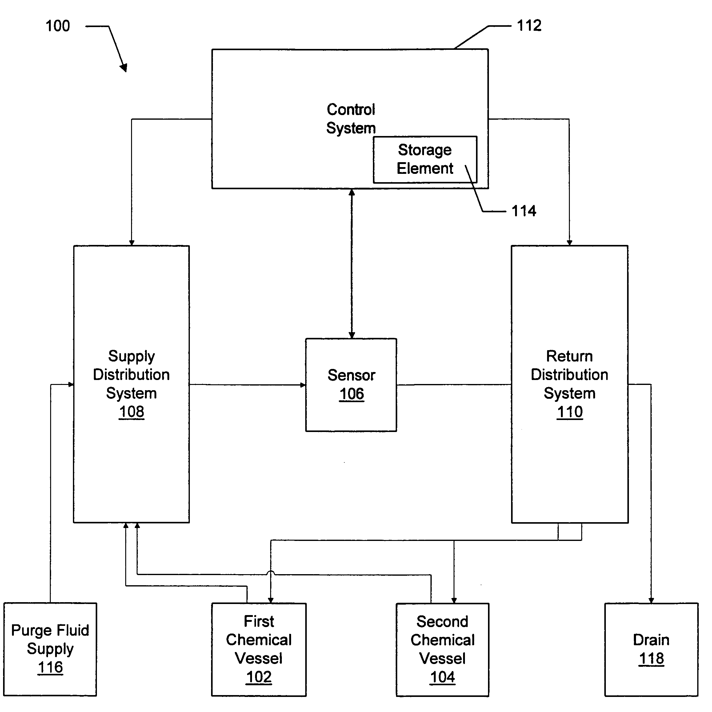
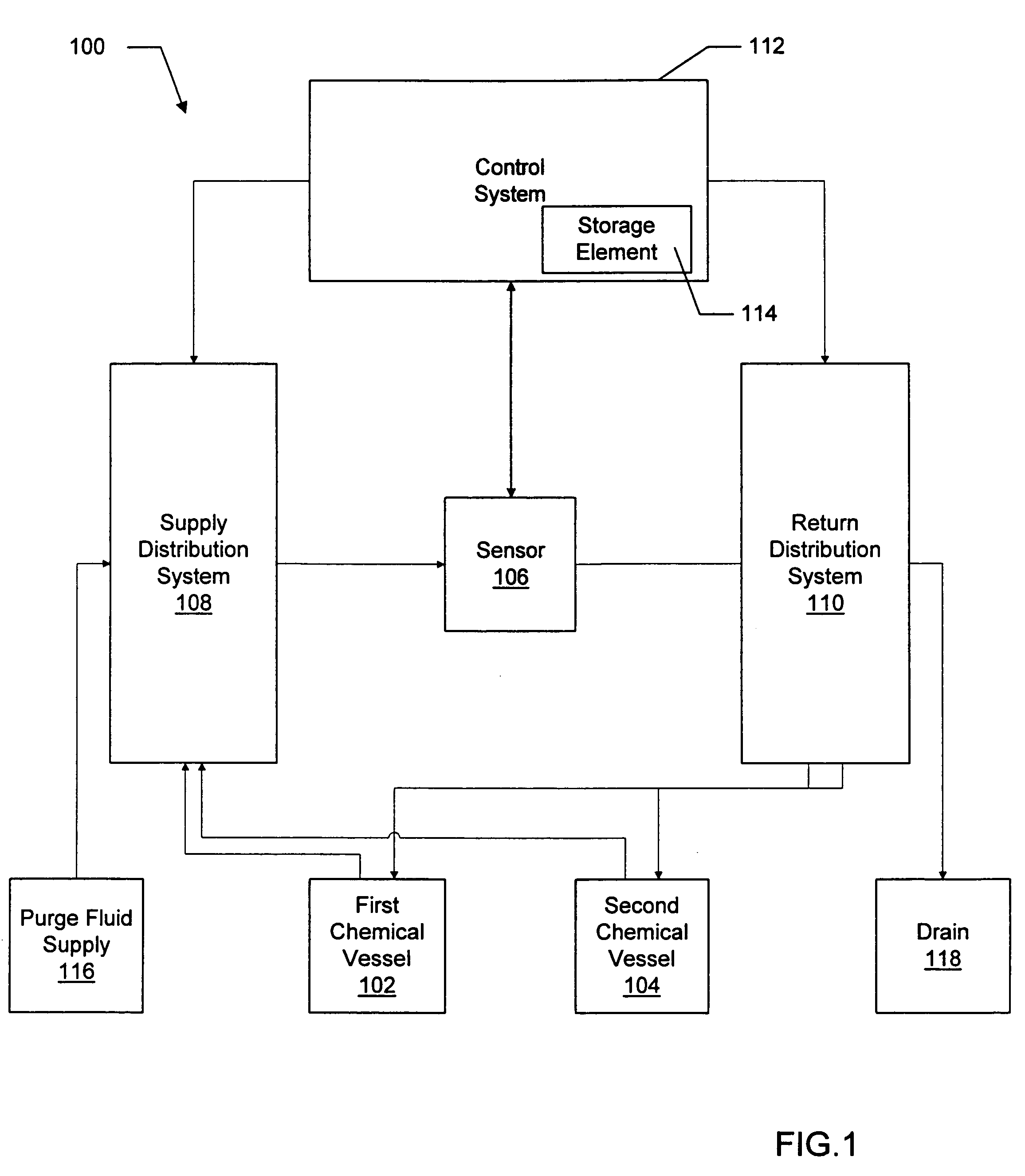
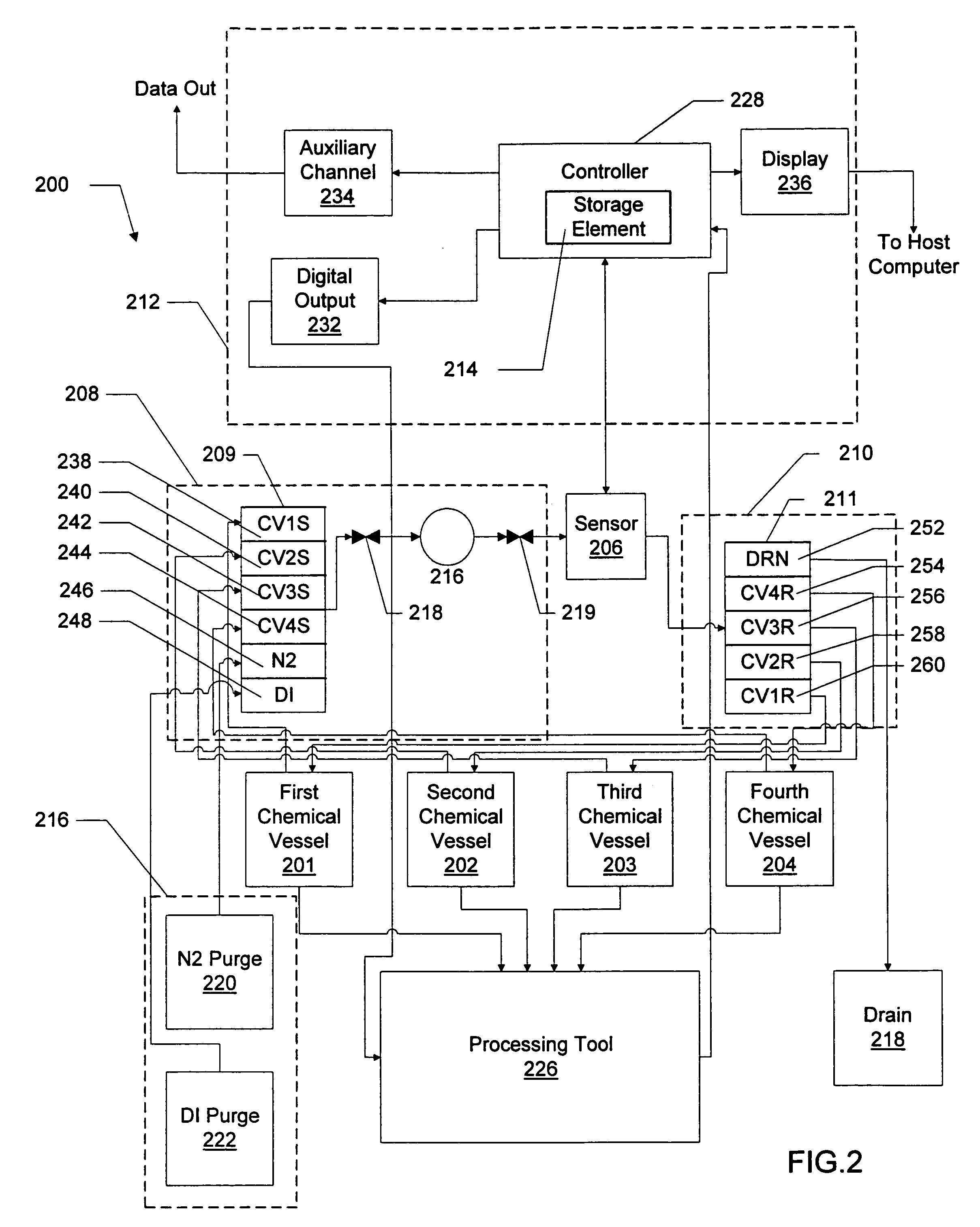
[0058]Referring now to the Drawings, FIG. 1 presents monitoring system 100. Monitoring system 100 is preferably configured to monitor one or more attributes of multiple chemical mixtures contained in multiple chemical vessels. In the embodiment shown in FIG. 1, monitoring system 100 includes a first chemical vessel 102 and a second chemical vessel 104. First chemical vessel 102 preferably contains a first chemical mixture. Likewise, second chemical vessel 104 preferably contains a second chemical mixture. In addition, monitoring system 100 preferably includes sensor 106. Sensor 106 is preferably configured to selectively receive a first sample flow of the first chemical mixture from the first chemical vessel and to selectively receive a second sample flow of the second chemical mixture from the second chemical vessel. Stated otherwise, sensor 108 is preferably configured within monitoring system 100 such that, during operation, sensor 106 may selectively receive sample flows from th...


PUM

PropertyMeasurementUnit
timeaaaaaaaaaa
timeaaaaaaaaaa
pre-control response timeaaaaaaaaaa

Abstract

A monitoring system is presented. The monitoring system may include a first chemical vessel containing a first chemical mixture and a second chemical vessel containing a second chemical mixture. The monitoring system may further include a sensor configured to selectively receive a first sample flow of the first chemical mixture from the first chemical vessel and a second sample flow of the second chemical mixture from the second chemical vessel. The sensor may be configured to measure a first sample attribute value of the first sample flow and a second sample attribute value of the second sample flow. By multiplexing multiple sample flows through a sensor, the monitoring system may monitor attributes of multiple chemical mixtures without requiring separate sensors for each chemical mixture monitored by the system.In an embodiment, the monitoring system is preferably configured to control an attribute of a chemical mixture. In such a case, the monitoring system may further include a control system configured to receive the first sample attribute value and the second sample attribute value from the sensor. The control system is further preferably configured to input the first sample attribute value into a first attribute control algorithm to calculate a first attribute control output. The first chemical mixture includes a first bulk attribute value, and the control system is preferably configured to direct the adjusting of the first bulk attribute value.

Description

BACKGROUND OF THE INVENTION[0001]1. Field of the Invention[0002]This invention relates to chemical processing and, more particularly, to systems and methods for monitoring attributes of multiple chemical mixtures using a single sensor, and further to systems and methods for controlling attributes of multiple chemical mixtures monitored by a single sensor, the systems and methods being especially configured for use in semiconductor processing.[0003]2. Description of the Related Art[0004]The information described below is not admitted to be prior art by virtue of its inclusion in this Background section.[0005]There is much that separates the wide variety of activities that constitute the field of chemical processing. One common thread between chemical processes, however, is the extent to which variations in the attribute values of the chemical mixtures used in these processes can influence process outcomes. Chemical processes are typically designed on the assumption that values of che...

Claims


Application Information

Patent Timeline
Patent Type & Authority Patents(United States)
IPC IPC(8): G01N30/00G01N1/00G01N35/08
CPCG01N35/08G01N35/1097Y10T436/2575
Inventor CAMPBELL, MARK A.TANG, PHUONG-ANHANDERSON, GARY R.
Owner ADVANCED MICRO DEVICES INC
Learn More