
Method for forming a fibers/composite material having an anisotropic structure

a composite material and fiber technology, applied in the field of fiber/composite material forming, can solve the problems of serious production problems in the commercialization of carbon nanotubes, and achieve the effects of enhancing the anisotropic structure of the extruder, significant potential, and enhancing the orientation/alignment of the fibers

Inactive Publication Date: 2007-04-03
THE BOARD OF RGT UNIV OF OKLAHOMA
View PDF1 Cites 17 Cited by
  • Summary
  • Abstract
  • Description
  • Claims
  • Application Information

AI Technical Summary

Benefits of technology

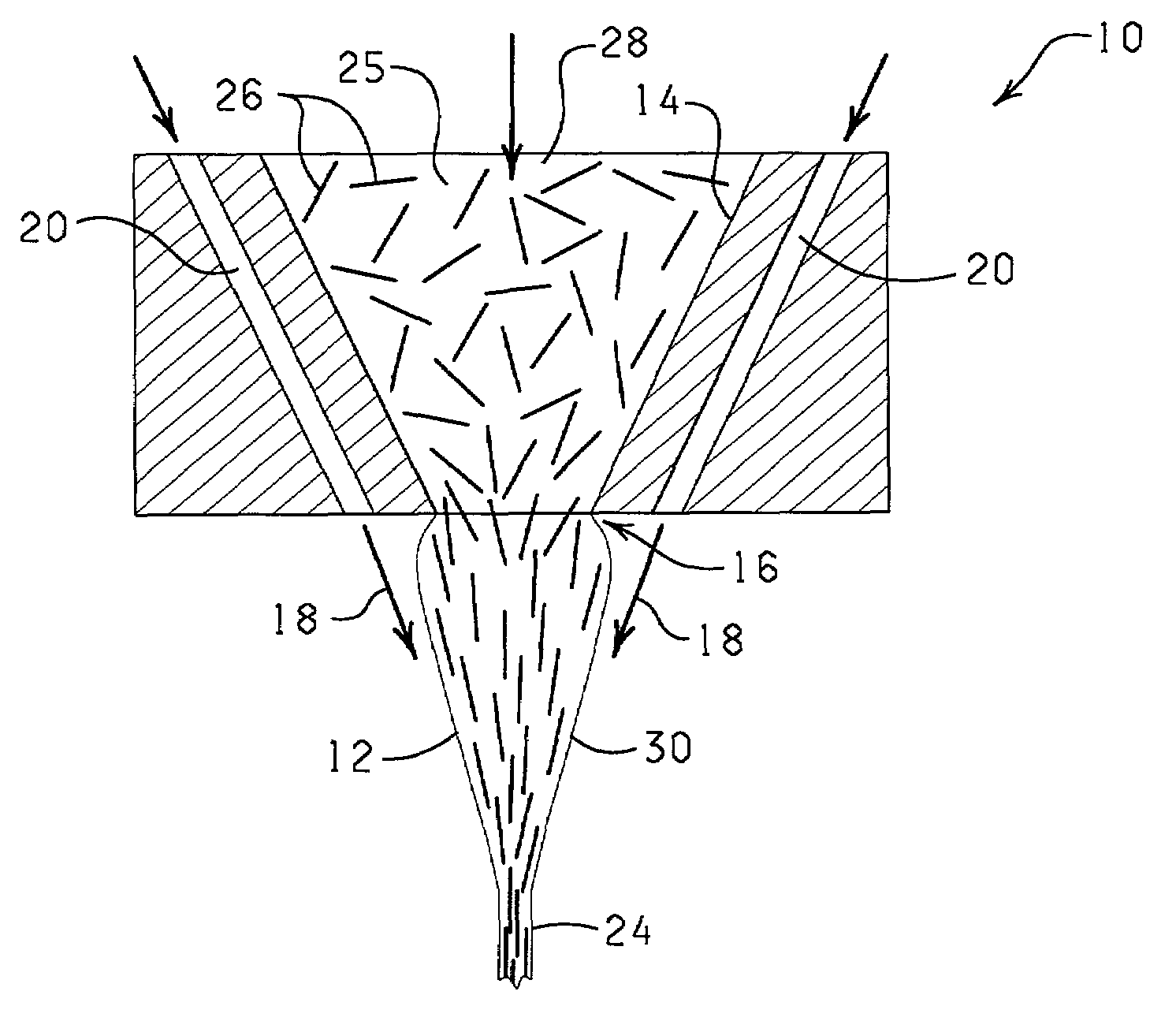
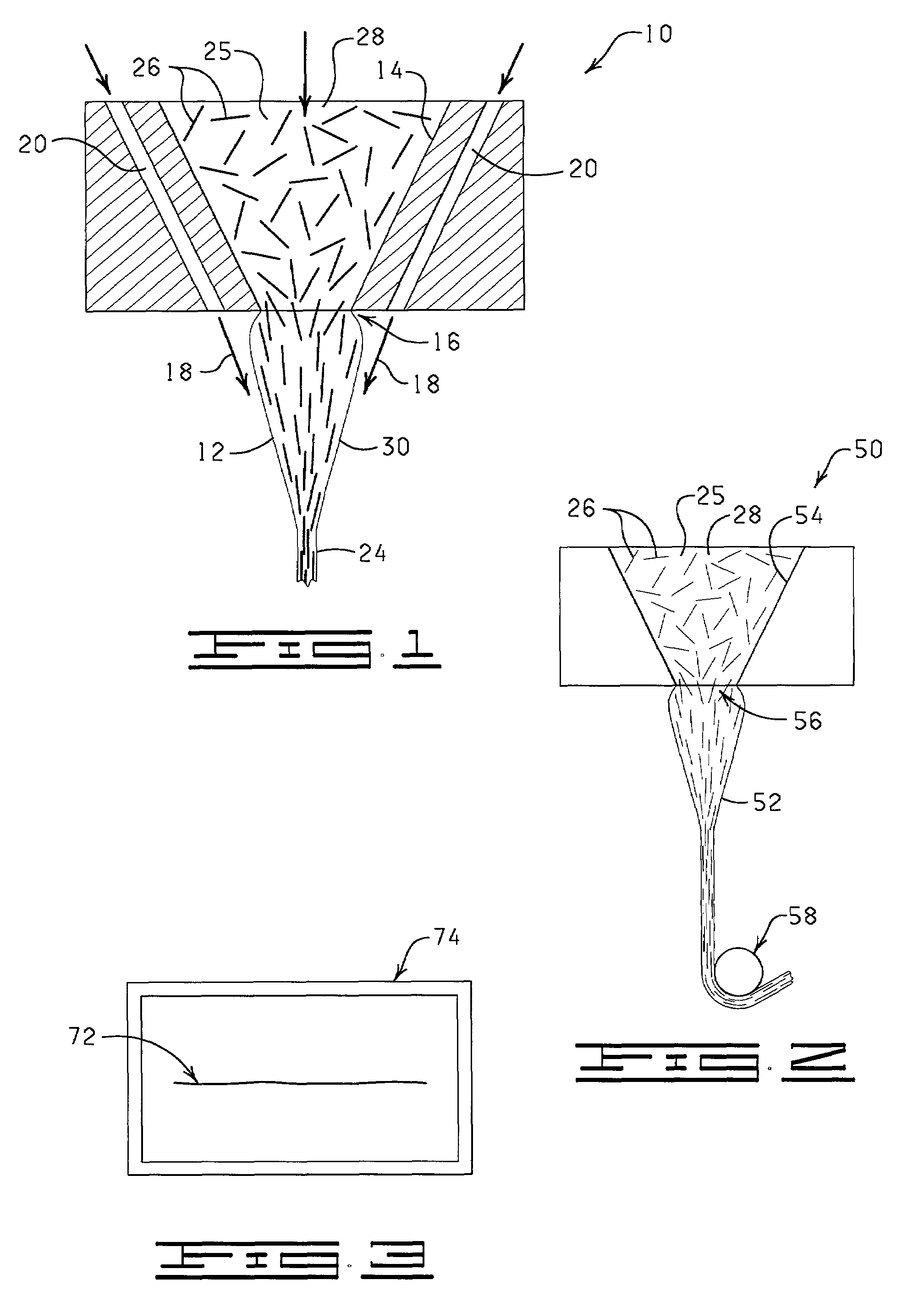
[0006]Broadly, the fibers / composite material is produced by mixing an effective amount of fibers with a matrix material to form a mixture containing from about 96 weight percent of the fibers to parts per billion (ppb) of the fibers and wherein the fibers are randomly oriented in the deformable mixture. The mixture is then passed through an orifice or capillary (e.g. extruded), or pulled or stretched to form an extrudate and to create an anisotropic structure, e.g. an enhanced orientation / alignment of the fibers along the longitudinal axis of the extrudate. Thereafter, pressure can be applied about the extrudate to substantially compress the fibers in the extrudate and to enhance the anisotropic structure of the extrudate. The fibers / composite material is a highly-moldable, composite material with significant potential in military applications and which by the proper choice of components may have desirable properties, such as ultra-strength, an increased conductivity orders of magnitude over that of even a normally conductive polymer, an increased semi-conductive property, or an enhanced optical property.

Problems solved by technology

Previous efforts to commercialize carbon nanotubes have revealed serious production problems.

Method used


Image

  • Method for forming a fibers/composite material having an anisotropic structure
  • Method for forming a fibers/composite material having an anisotropic structure

Examples


Embodiment Construction

[0011]The present invention is a method for producing fibers / composite material having an anisotropic structure which can be commercially produced utilizing commercially available equipment. In general, effective amounts of fibers are mixed with a matrix material to form a deformable mixture containing less than about 96 weight percent of the fibers to about parts per billion of the fibers and wherein the fibers are randomly oriented in the deformable mixture. The liquid mixture is then passed through an orifice or a capillary (e.g. extruded) to form an extrudate. Shear attenuation pressure is applied about the extrudate, either as the extrudate passes through the orifice or capillary, and / or after the extrudate passes through the orifice or capillary, to substantially compress the fibers in the extrudate and to provide the fibers / composite material having an anisotropic structure, e.g. the fibers / polymer material is substantially aligned with the longitudinal axis of the extrudate....


PUM

PropertyMeasurementUnit
Percent by massaaaaaaaaaa
Pressureaaaaaaaaaa

Abstract

A method for forming fibers / composite material having an anisotropic structure, comprising the steps of mixing an effective amount of fibers with a matrix material to form a deformable mixture containing less than about 96 weight percent of the fibers to about parts per billion of the fibers and wherein the fibers are randomly oriented in the deformable mixture. The deformable mixture can be extruded, stretched or otherwise deformed to form an extrudate. Pressure is applied about the extrudate to substantially compress the fibers in the extrudate to provide the fibers / composite material having an anisotropic structure.

Description

CROSS-REFERENCE TO RELATED APPLICATIONS[0001]The present application is a continuation of U.S. Ser. No. 09 / 374,775, filed Aug. 16, 1999, entitled METHOD FOR FORMING A FIBERS / COMPOSITE MATERIAL HAVING AN ANISOTROPIC STRUCTURE, the entire content of which is hereby expressly incorporated herein by reference.STATEMENT REGARDING FEDERALLY SPONSORED RESEARCH AND DEVELOPMENT[0002]Not applicable.BACKGROUND OF THE INVENTION[0003]Innovations in materials have driven much of the technological progress throughout the century. Today, the potential applications of a new unforeseen pure molecular form of carbon known as carbon nanotubes, is engendering tremendous excitement across the scientific community. Since their discovery, reports of their ever more outstanding and exciting properties seems to foreshadow the advent of the new and quite remarkable carbon age. Many countries have now identified such molecules as a strategic commodity and are making major commitments toward their production. S...

Claims


Application Information

Patent Timeline
IPC IPC(8): C01B31/02B29C48/05B29C70/14C08K7/02D01F1/10D01F6/04D01F6/06
CPCB29C47/0004B29C70/12B29C70/14C08K7/02D01F1/10D01F6/04D01F6/06B29C47/0014B29K2023/06B29K2023/12B29K2025/00B29K2077/00B29K2105/06B29K2707/04B82Y30/00Y10S977/742Y10S977/734Y10S977/842Y10S977/847Y10S977/844Y10S977/753D01D5/0985B29C48/05B29C48/022
Inventor NEWMAN, GERARD K.SHAMBAUGH, ROBERT L.HARWELL, JEFFREY H.
Owner THE BOARD OF RGT UNIV OF OKLAHOMA
Learn More