
Height adjustable work chair

a work chair and height adjustment technology, applied in the direction of chairs, movable seats, machine supports, etc., can solve the problems of inefficiency of current chair designs, user awkward position,

Inactive Publication Date: 2007-04-03
LARSON JOHN E
View PDF8 Cites 24 Cited by
  • Summary
  • Abstract
  • Description
  • Claims
  • Application Information

AI Technical Summary

Benefits of technology

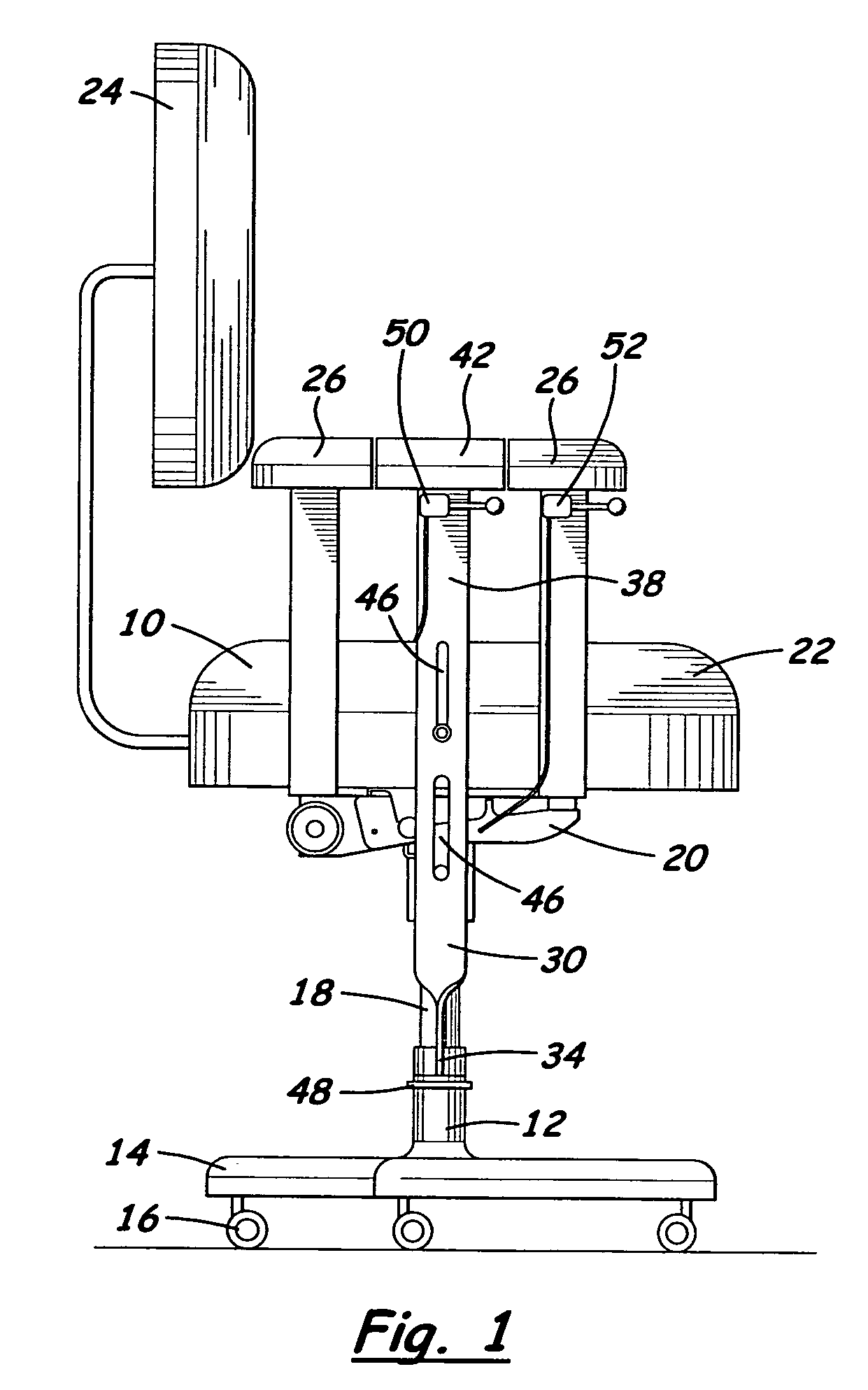
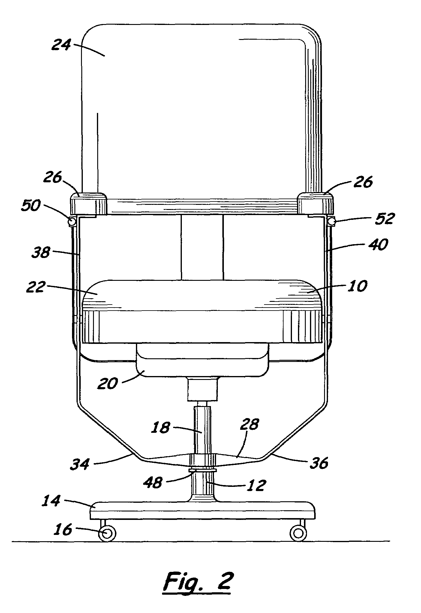
[0004]The invention involves height adjustable work chairs from which seated persons need not remove their body weight from the chair during upward height adjustment, that with current chair designs, would awkwardly position the person relative to the task to which the adjustment is being made. Push-off arm rests can support all or part of a user's weight independent of the height adjustment mechanism, allowing the chair seat to be adjusted upwardly. The chair has an upper portion that moves relative to a lower stationary portion supported on the floor. The push-off arm rests are directly connected to the lower portion allowing the body weight of the chair user to be transferred from the chair seat to the floor in a way that reduces downward force to the height adjustment mechanism without the necessity of user's feet depending contact with the floor surface, as is the requirement with current chair designs. In the most preferred embodiment, a remote actuation mechanism is mounted proximate one of the push-off arm rests which allow the chair user to actuate a spring loaded height adjustment mechanism while at the same time using the push-off arm rests to transfer user's body weight away from the spring loaded height adjustment mechanism which can then resiliently power the chair set upwardly.

Problems solved by technology

This puts the chair user in an awkward position, especially in a way that relates to positioning her or his height to a specific work task.
If, for example, the multi-user chair were used in a laboratory setting to seat multiple users at a microscope, it may sometimes be necessary for a user to adjust the height of the chair to obtain appropriate eye level for the ocular setting due to limitations of the ocular setting on the microscope.
With chairs currently available, the awkward maneuver required for adjusting the height of the chair upwardly, more or less necessitates that the user speculate how far up to adjust the chair while employing trial and error to obtain the sought after adjustment.
In office settings, this same inefficiency with current chair designs exists, but is less noticeable due to lesser functional requirements demanded by the work task, or by the worker.

Method used


Image

  • Height adjustable work chair
  • Height adjustable work chair
  • Height adjustable work chair

Examples


Embodiment Construction

[0011]Push-off arm rests allow a seated person to remove their weight from the chair seat so the position of the seat can be adjusted without the seated person having to stand or leave the chair.

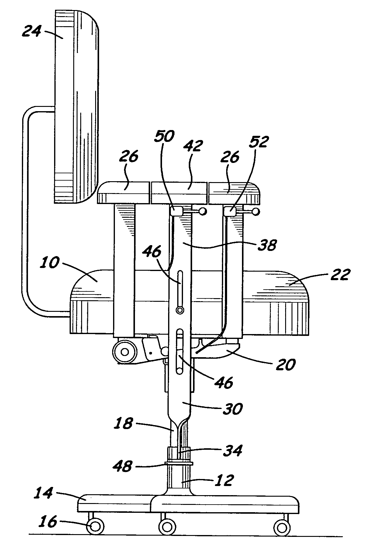
[0012]A preferred embodiment of the height adjustable work chair is shown in FIGS. 1–4. The height adjustable work chair of the subject invention has a push-off arm rest which allows one seated on the chair to lift their weight off the chair seat so the seat can be raised. The chair has an upper portion 10 and a lower portion 12. The upper portion moves relative to the lower portion. The lower portion 12 includes a floor contacting base 14. In the exemplified embodiment, the base 14 has castors 16. The upper portion 10 moves relative to the lower portion 12 by a height adjustment mechanism 18. The height adjustment mechanism is supported by the base 14 and supports a seat support mechanism 20 which supports the seat 22 of the chair. The seat support mechanism 20 and the chair seat 22 move re...


PUM


Abstract

A height adjustable chair has an upper portion that moves relative to a lower portion. Push-off arm rests are provided so that a person need not leave the chair to adjust the seat height upwardly. A seated person can transfer their body weight to the push-off arm rests supported directly by the stationary lower portion while the seat is being adjusted upwardly.

Description

CROSS-REFERENCE TO RELATED APPLICATIONS[0001]The subject application claim the benefits of U.S. Provisional Application Ser. No. 60 / 513,787, filed Oct. 23, 2003 and U.S. Provisional Application Ser. No. 60 / 513,788, filed Oct. 23, 2003. These applications are herein incorporated by reference in their entirety.BACKGROUND OF THE INVENTION[0002]Height adjustable work chairs are standard in today's seated workplace environments. The most common height adjustment mechanism for work chairs utilizes a spring driven mechanism, most commonly, the locking gas spring. Since a spring driven height adjustment mechanism only powers the chair seat upwardly when the chair user reduces downward force to the spring which supports the chair seat, the maneuver for current chair design requires the chair user's legs to lift the chair user from the chair seat while the chair user awkwardly reaches with one hand to locate and lift an unmarked height adjustment lever which is usually located out of user's v...

Claims


Application Information

Patent Timeline
Patent Type & Authority Patents(United States)
IPC IPC(8): A47C1/00
CPCA47C3/22A47C7/54A47C9/005
Inventor LARSON, JOHN E.
Owner LARSON JOHN E
Learn More