Sequential injection lubrication system for a spherical rotary valve internal combustion engine operating on natural gas or alternative fuels

a rotary valve, natural gas or alternative fuel technology, applied in the direction of oscillatory slide valves, machines/engines, mechanical equipment, etc., can solve the problems of affecting the compression of the respective cylinder, the integrity of the surface of the cylinder, and the life expectancy of the components only a few months,

Inactive Publication Date: 2007-04-03
COATES GREGORY
View PDF4 Cites 5 Cited by
  • Summary
  • Abstract
  • Description
  • Claims
  • Application Information

AI Technical Summary

Benefits of technology

[0010]Another object of the present invention is to provide a novel apparatus for allowing a user to program the intermittent sequential lubrication system as needed for the internal combustion engine operating on natural gas or alternative fuels, such as bio fuels.
[0012]A sequential injection lubrication system for a spherical rotary valve internal combustion engine operating on natural gas or alternative fuels, the lubrication system having a plurality of injectors, one for each cylinder, the injectors and communication with a lubricant reservoir and with a control unit which sequentially opens and closes the injectors for the introduction of lubricant into the cylinder, the control unit in communication with a control panel allowing the selective setting of the duration of the pulse injection and the frequency thereof.

Problems solved by technology

Engines of this type would normally operate around the clock and suffer extensive wear and tear from the high heat of combustion and acidity of the raw natural gas such that the life expectancy of their components was only a few months.
The wear and tear is contributed by the fact that the raw natural gas is a very dry, acidic fuel which burns at a very high temperature and under high compression such that normal poppet valves would quickly become scorched and brittle and the compression ring on the piston would also become scorched and brittle affecting the compression of the respective cylinder and affecting the integrity of the surface of the cylinder bore.
However, the compression ring on the pistons were still being affected by the high temperature and high compression of the raw, acidic natural gas fuel, such that the scorching and degradation of the internal cylinder wall was still occurring.

Method used


Image

  • Sequential injection lubrication system for a spherical rotary valve internal combustion engine operating on natural gas or alternative fuels
  • Sequential injection lubrication system for a spherical rotary valve internal combustion engine operating on natural gas or alternative fuels
  • Sequential injection lubrication system for a spherical rotary valve internal combustion engine operating on natural gas or alternative fuels

Examples


Embodiment Construction

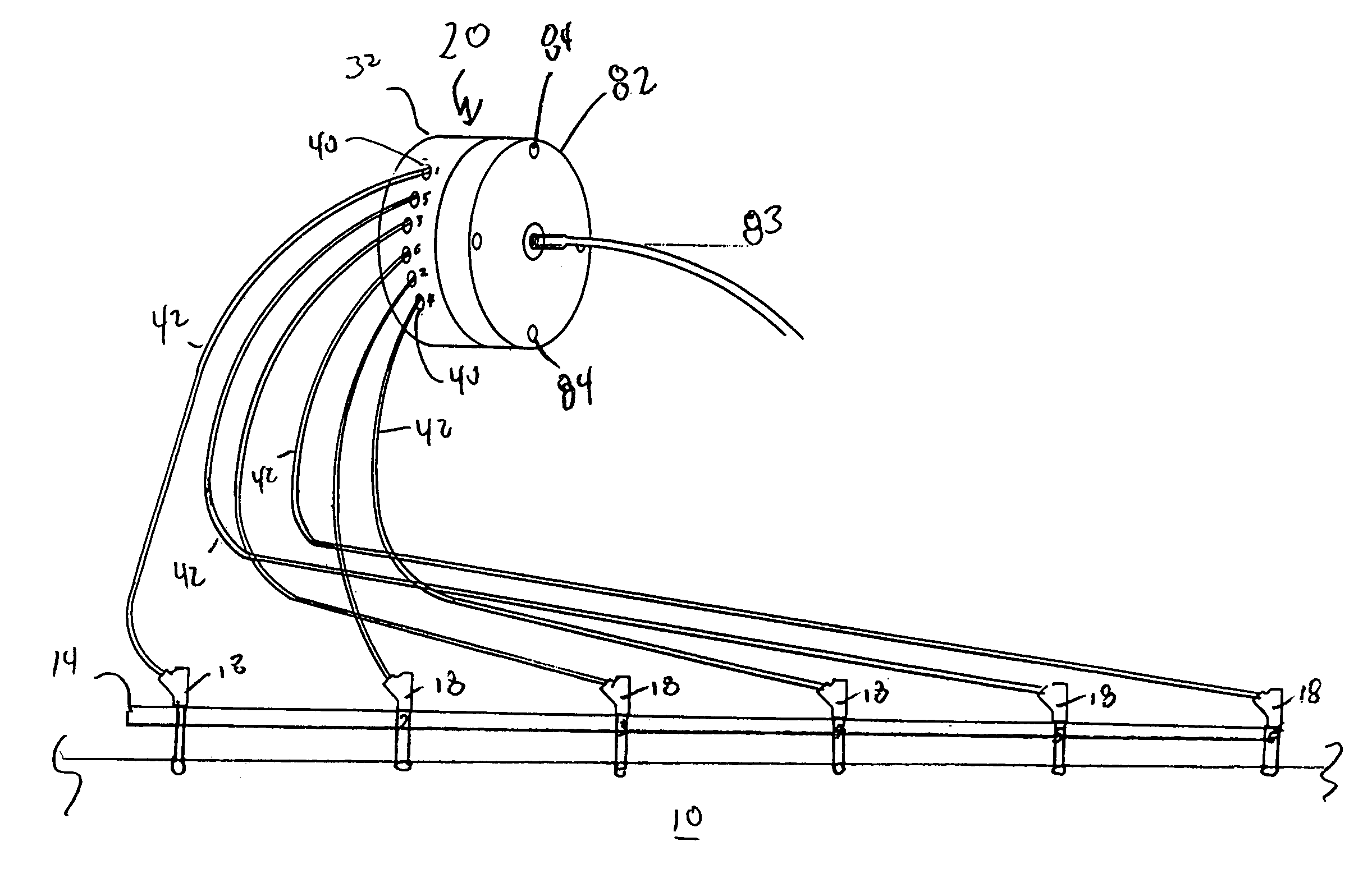
[0017]FIG. 1 is a schematic of the lubrication system of the present invention. For purposes of example, the engine will be described as a straight six diesel engine 10 being fueled by natural gas, but it will be understood that alternative fuels, such as bio-fuels, may also fuel the engine. In the instant situation, the engine 10 is being used to run a generator (not shown) which in turn generates electricity which is sold to the local electrical grid. A lubricant reservoir 12 is in communication 13 with a high pressure lubricant rail 14 by means of pump 16 thereby insuring that the lubricant rail is filled with lubricant. The lubricant rail 14 in turn is in communication with a plurality of injectors 18, there being at least one injector 18 for each cylinder of the engine 10. The injectors in turn are in communication with a sequential injection control unit 20 which in turn is in communication 21 with an operation panel 22. The operation panel 22 can be either set manually or rem...


PUM


Abstract

A sequential injection lubrication system for a spherical rotary valve internal combustion engine operating on natural gas or alternative fuels, the lubrication system having a plurality of injectors, one for each cylinder, the injectors and communication with a lubricant reservoir and with a control unit which sequentially opens and closes the injectors for the introduction of lubricant into the cylinder, the control unit in communication with a control panel allowing the selective setting of the duration of the pulse injection and the frequency thereof.

Description

BACKGROUND OF THE INVENTION[0001]1. Field of the Invention[0002]The present invention relates to internal combustion engines, and in particular, high compression internal combustion engines which operate on natural gas, raw natural gas, or alternative fuels such as bio-fuels, and more particularly, to a selective sequential automatic lubricating system for lubricating the cylinder and compression ring on the piston to extend the life of the engine.[0003]2. Description of the Prior Art[0004]Conventional internal combustion engines of the piston, cylinder and poppet valve variety are normally constructed with an oil sump and pump which lubricates all of the moving parts of the engine in order to lessen the wear and tear on the engine. The lubricating points would include, but would not be limited to, the poppet valve stems, the cylinder walls below the compression ring of the piston, and the crank shaft. Still further, the conventional internal combustion engine runs on gasoline or di...

Claims


Application Information

Patent Timeline
IPC IPC(8): F02B43/00
CPCF01L7/10F01L7/16F01L7/18F01M1/14
Inventor COATES, GREGORY
Owner COATES GREGORY
Why Eureka
Try Eureka