Eureka AIR delivers breakthrough ideas for toughest innovation challenges, trusted by R&D personnel around the world.

Temperature correction of wigglers and undulators

a technology of undulator and temperature correction, which is applied in the direction of magnets, cores/yokes, magnets, etc., can solve the problems of motors and electronics that are required to achieve high accuracy and precision, the performance variation of fel or sr sources is not acceptable, and the apparatus usually needs high accuracy and precision. achieve the effect of simple and inexpensiv

Inactive Publication Date: 2007-03-27
STI OPTRONICS
View PDF7 Cites 19 Cited by
  • Summary
  • Abstract
  • Description
  • Claims
  • Application Information

AI Technical Summary

Benefits of technology

[0010]The present invention proposes a novel method of temperature compensation, which is simple, inexpensive, can adjust both field strength variations and centerline shifts due to temperature fluctuations, and can be used with all types of undulators. Furthermore, the present method is continuously tunable, iterative, and convergent. Unlike the prior methods that consisted of using entirely mechanical means to correct for temperature variations, the present invention is directed to providing magnetic means to correct for the temperature variations.
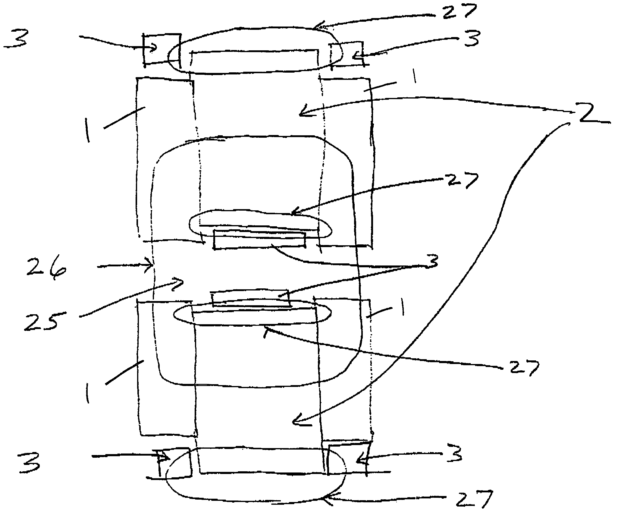
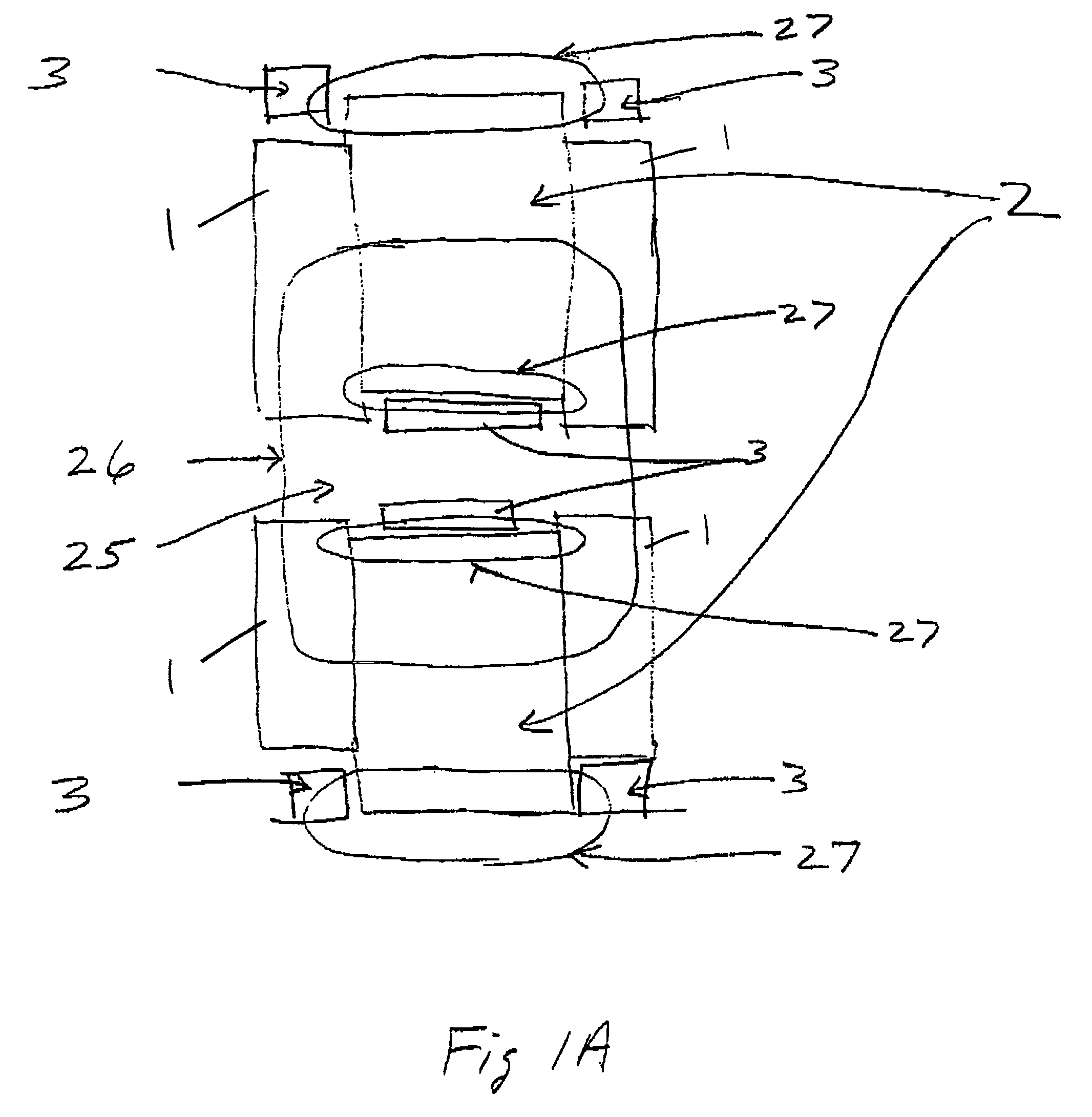
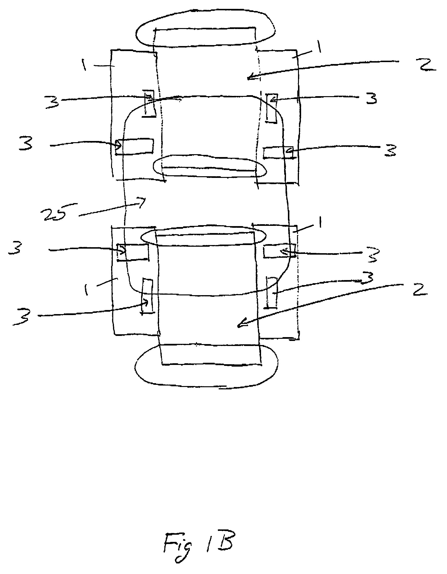
[0018]According to yet another aspect of the present method, the temperature-compensating material is applied to be associated with only a subset of the magnets, wherein the subset means one or more magnets less than the entire magnets. This method is effective in producing a local temperature-dependent variation to compensate for a temperature-dependent local change in the magnetic field. According to still another aspect, the temperature-compensating material may be specifically shaped so as to additionally achieve the shimming effect of tuning the magnetic field to correct for temperature-dependent field errors.

Problems solved by technology

These temperature dependencies can cause unacceptable performance variations of the FEL or SR source.
This is quite difficult as undulators can weigh several tons and be several meters long.
In addition, many applications require micron level control of the movement, so the apparatus usually needs high accuracy and precision.
Yet, the motors and electronics required to achieve high accuracy and precision can be exposed to high radiation levels in the undulator's operating environment, and this radiation can easily cause failure of the motors and / or electronics.
Radiation resistant equipment can be very expensive and complex, and not always available.
Titanium is very expensive, difficult to machine, and has mechanical creep over time.
In addition, since the differences in the thermal expansion coefficients for the different materials are large, there are many induced stresses in the mechanical structure.
These lead to deformations, lack of predictability, stiction, twist, warp, and other mechanical problems.
Engineering solutions to these problems are challenging and do not always work.
In short, this prior method is complex, expensive, hard to engineer, and furthermore, has no means of correcting for design deficiencies.
Either this approach would work, or the entire design would need to be changed and iterated to make it work, and yet this process may not converge due to the inherent complexity of the approach.

Method used


Image

  • Temperature correction of wigglers and undulators
  • Temperature correction of wigglers and undulators
  • Temperature correction of wigglers and undulators

Examples


examples

[0063]Some examples are shown in reference to FIGS. 2–9 to illustrate the use of compensating materials to adjust for dB / dT and d(centerline) / dT. In these figures, the compensating materials are in a parallel flux shunt configuration. The analysis method is finite element analysis (FEA). The magnetic model is shown in FIG. 2, illustrating a half pole 1b (i.e., half of the pole as seen along the direction of the undulator as shown in FIG. 10) coupled to a half magnet 2b. Toward the “back”23 of the half magnet 2b, i.e., the side away from the mechanical centerline 22 of the undulator, a half compensating material 3b is arranged. Boundary conditions are used to provide a periodic magnetic field. The FEA is two dimensional, but the principles are easily extended to three dimensions, and three-dimensional embodiments will be explicitly described in reference to FIGS. 10–14 later.

[0064]Referring to FIG. 3, the magnetic flux lines 17 of the half magnet 2b of FIG. 2 are shown. The flux line...


PUM


Abstract

An undulator includes a periodic arrangement of magnets to produce a periodic spatial magnetic field distribution in a magnetic gap defined by the magnets. The undulator further includes a temperature-compensating material selectively arranged to compensate for a temperature-dependent change in the magnetic field of the undulator. The change may be in the strength of the magnetic field, or in the position of the magnetic field centerline. According to one aspect of the invention, the temperature-compensating material is movably arranged, so as to fine tune its compensation effect after it is initially arranged. Alternatively or additionally, the amount of temperature-compensating material may be adjusted to fine tune its compensation effect after it is initially arranged.

Description

CROSS-REFERENCE TO RELATED APPLICATION[0001]This application claims the benefit of U.S. Provisional Application No. 60 / 409,291, filed Sep. 6, 2002.FIELD OF THE INVENTION[0002]The invention is directed generally to wigglers and undulators, and more specifically to means for compensating for the magnetic field strength change and / or the magnetic centerline shift in the wigglers and undulators due to temperature variations.BACKGROUND OF THE INVENTION[0003]Wigglers and undulators are magnetic assemblies used in synchrotron radiation (SR) sources and free electron lasers (FEL's). An exploded view of a wiggler / undulator can be found in FIG. 10. The terms wiggler and undulator are used interchangeably, and in the present application the term undulator is used to refer to both. Briefly, an undulator consists of a pair of opposing magnet arrays, which create an oscillating magnetic field in the gap separating the arrays (i.e., the gap between the arrays). A high-energy electron beam passing ...

Claims


Application Information

Patent Timeline
Patent Type & Authority Patents(United States)
IPC IPC(8): H01J23/087
CPCH05H7/04
Inventor GOTTSCHALK, STEPHEN C.
Owner STI OPTRONICS
Why Eureka
Eureka Blog
Learn More