
Method and system for performing static timing analysis on digital electronic circuits

a technology of static timing analysis and digital electronic circuits, applied in the field of software tools for verifying integrated circuit designs, can solve the problems of real timing violation that cannot be detected during static timing analysis, and may not even be realized

Inactive Publication Date: 2007-03-20
IBM CORP
View PDF10 Cites 14 Cited by
  • Summary
  • Abstract
  • Description
  • Claims
  • Application Information

AI Technical Summary

Benefits of technology

The present invention provides a method for analyzing a final circuit netlist and determining if it meets timing constraints. The method includes static timing analysis and formal verification. A snip file is generated based on non-critical timing signals and paths that have been selected not to be checked during static timing analysis. The final circuit netlist is then analyzed using the snip file. If the netlist passes formal verification, it can proceed to manufacturing. If not, the user has to modify certain snip points or the circuit netlist and perform the analysis again. The technical effect of the invention is to improve the accuracy and efficiency of analyzing final circuit netlists and ensuring they meet timing constraints.

Problems solved by technology

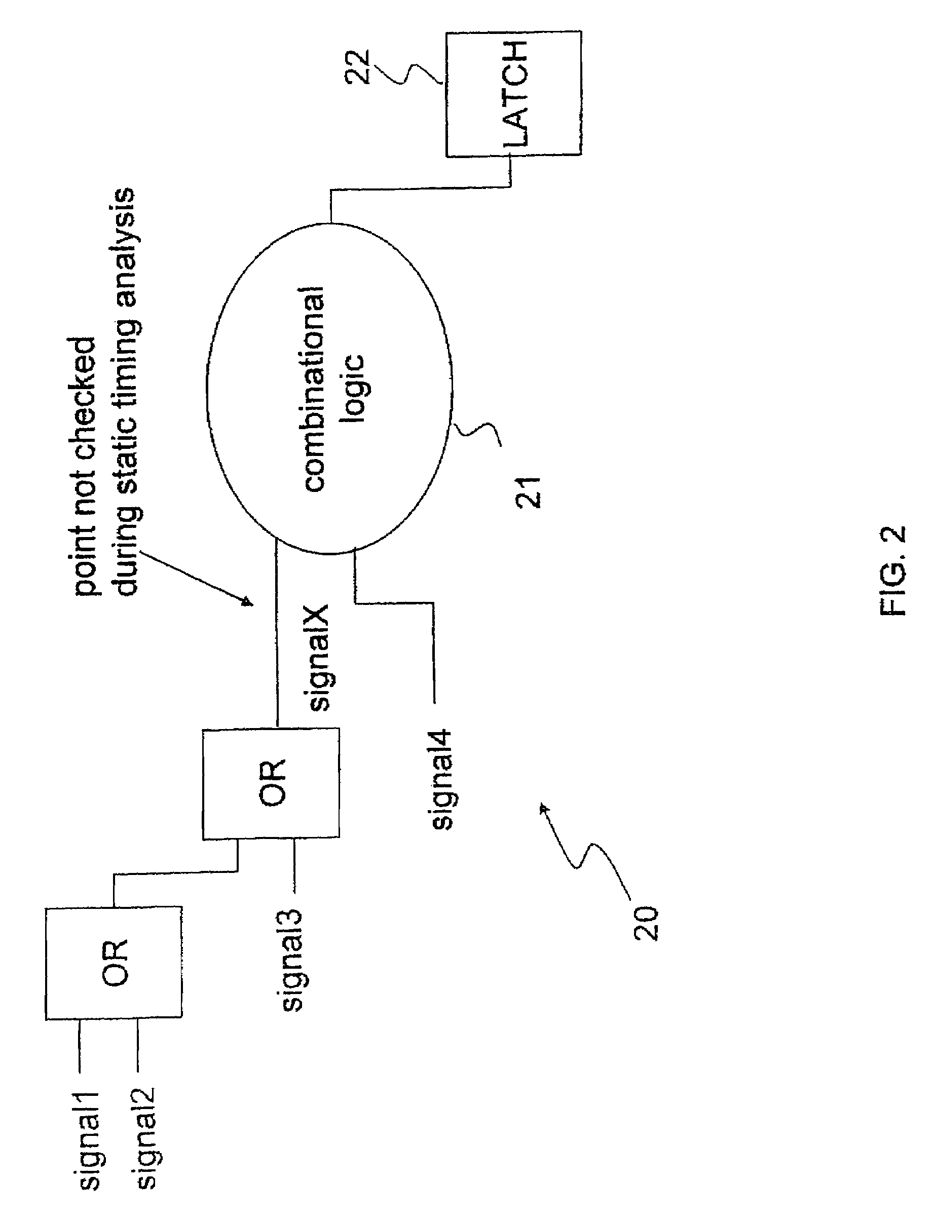
However, when the critical timing paths of some circuit designs are masked as part of the cone of logic of the eliminated non-critical timing paths, the elimination of the non-critical timing paths could lead to a real timing violation to go undetected during static timing analysis.
The real timing violation may not even be realized until actual hardware is manufactured.

Method used


Image

  • Method and system for performing static timing analysis on digital electronic circuits
  • Method and system for performing static timing analysis on digital electronic circuits
  • Method and system for performing static timing analysis on digital electronic circuits

Examples


Embodiment Construction

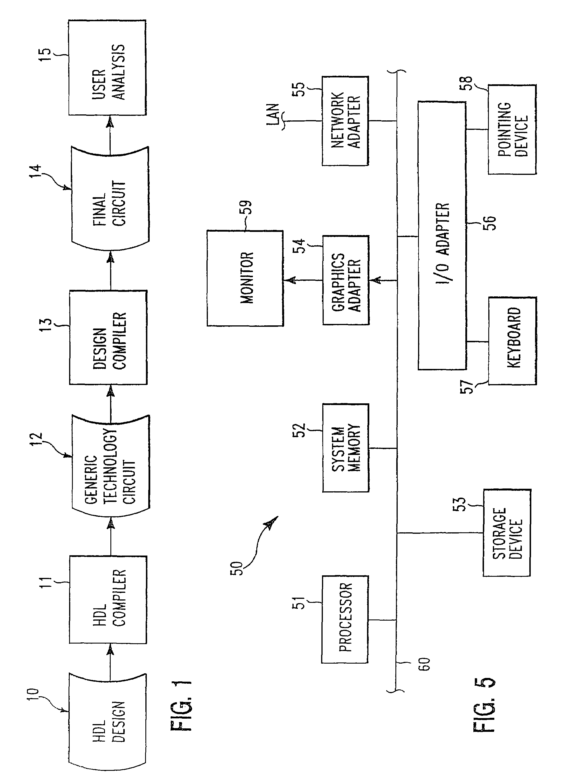
[0015]Referring now to the drawings and in particular to FIG. 1, there is illustrated a high-level logic flow diagram of a design environment, in accordance with a preferred embodiment of the present invention. As shown, a hardware description language (HDL) compiler 11 translates a high-level description of a digital circuit design, such as a HDL design 10, into a generic technology circuit netlist 12. A design compiler 13 then translates generic technology circuit netlist 12 into a final circuit netlist 14. Final circuit netlist 14 is an optimized implementation of HDL design 10 in accordance with a specific processing technology. Final circuit netlist 14 is subsequently subjected to an user analysis 15 by a circuit designer in order to explore various aspects of the final circuit's performance that may not have been completely addressed by design compiler 13.

[0016]At the level of HDL design 10, the circuit design is described in a high-level language such as Verilog HDL. The desi...


PUM


Abstract

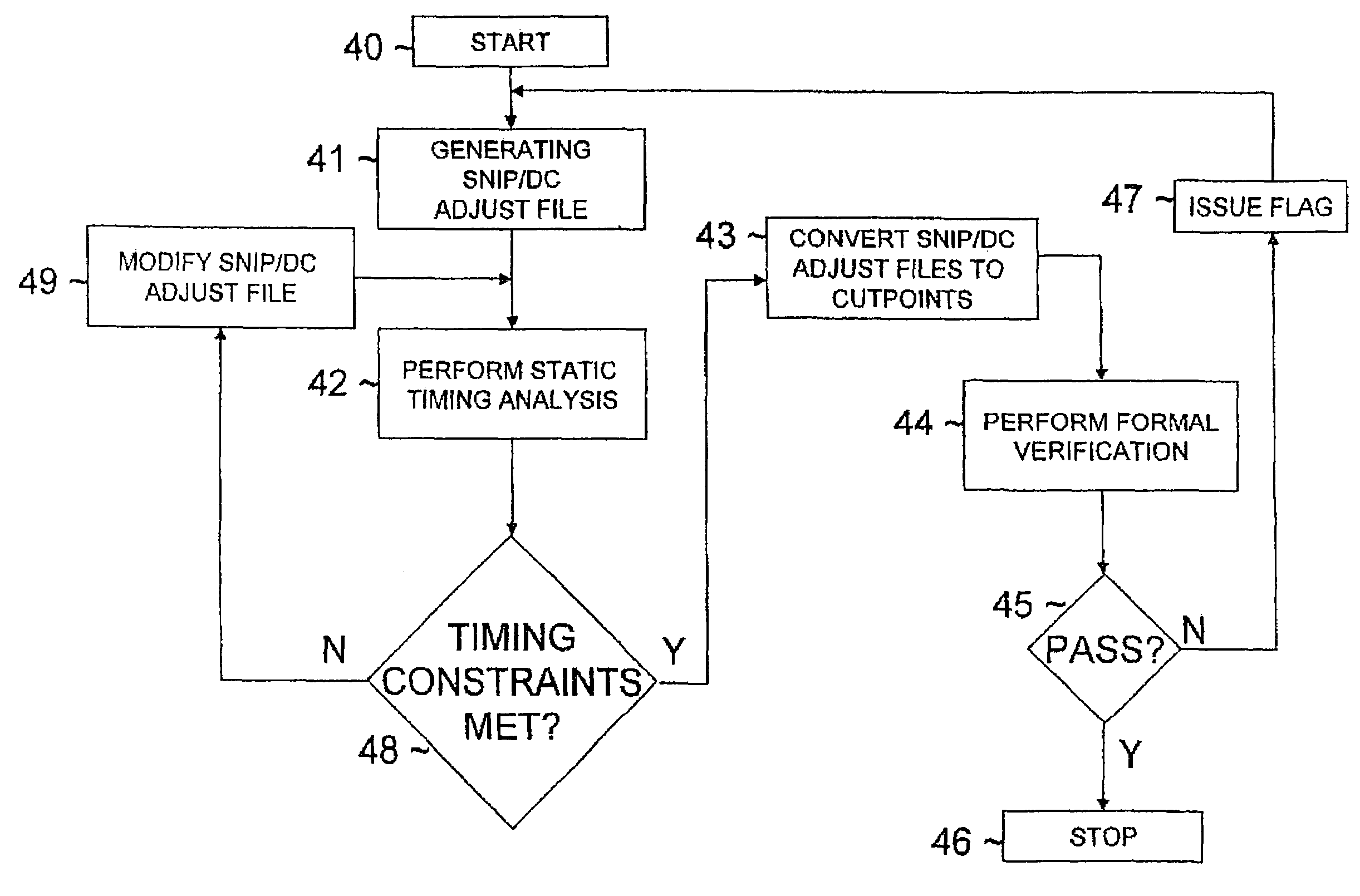
A method for performing static timing analysis on digital electronic circuits is disclosed. A snip (or DC adjust) file is initially generated. Static timing analysis is then performed on the final circuit netlist using the snip file. If the final circuit netlist meets all the timing constraints, the snip file is converted to a group of cutpoints, and formal verification is performed on the cutpoints. A determination is made as to whether or not the cutpoints pass formal verification. If the cutpoints pass formal verification, the user analysis on the final circuit netlist is completed, and the final circuit netlist can proceed to manufacturing. Otherwise, if the cutpoints do not pass formal verification, a flag is issued to alert a user. The user then has to either modify certain snip point(s) within the snip file or modify the circuit netlist, and perform the user analysis again.

Description

BACKGROUND OF INVENTION[0001]1. Technical Field[0002]The present invention relates to software tools in general, and, in particular, to software tools for verifying integrated circuit designs. Still more particularly, the present invention relates to a method and system for performing static timing analysis on digital electronic circuits.[0003]2. Description of Related Art[0004]In the field of integrated circuit (IC) design, digital electronic circuits are initially represented by a high-level abstraction written in hardware description language (HDL).[0005]The HDL representation allows a circuit designer to express all the desired functionality of a digital electronic circuit at the register transfer level (RTL) of abstraction.[0006]The HDL representation is then converted into a circuit file through a process known as synthesis that involves translation and optimization. Finally, static timing analysis and formal verification are performed on the circuit file. Static timing analys...

Claims


Application Information

Patent Timeline
Patent Type & Authority Patents(United States)
IPC IPC(8): G06F17/50
CPCG06F17/5031G06F30/3312
Inventor CHARLEBOIS, STEVEN E.SALEM, GERARD M.
Owner IBM CORP
Learn More