
Triggered packet data rate change in a communication system

a communication system and packet data technology, applied in data switching networks, instruments, frequency-division multiplexes, etc., can solve the problems of reducing the total number of users that may be simultaneously supported, finite resources available to provide such services, etc., to achieve high data rate capacity, data rate, and the effect of efficient utilization of radio access network resources

Inactive Publication Date: 2007-03-20
TELEFON AB LM ERICSSON (PUBL)
View PDF9 Cites 59 Cited by
  • Summary
  • Abstract
  • Description
  • Claims
  • Application Information

AI Technical Summary

Benefits of technology

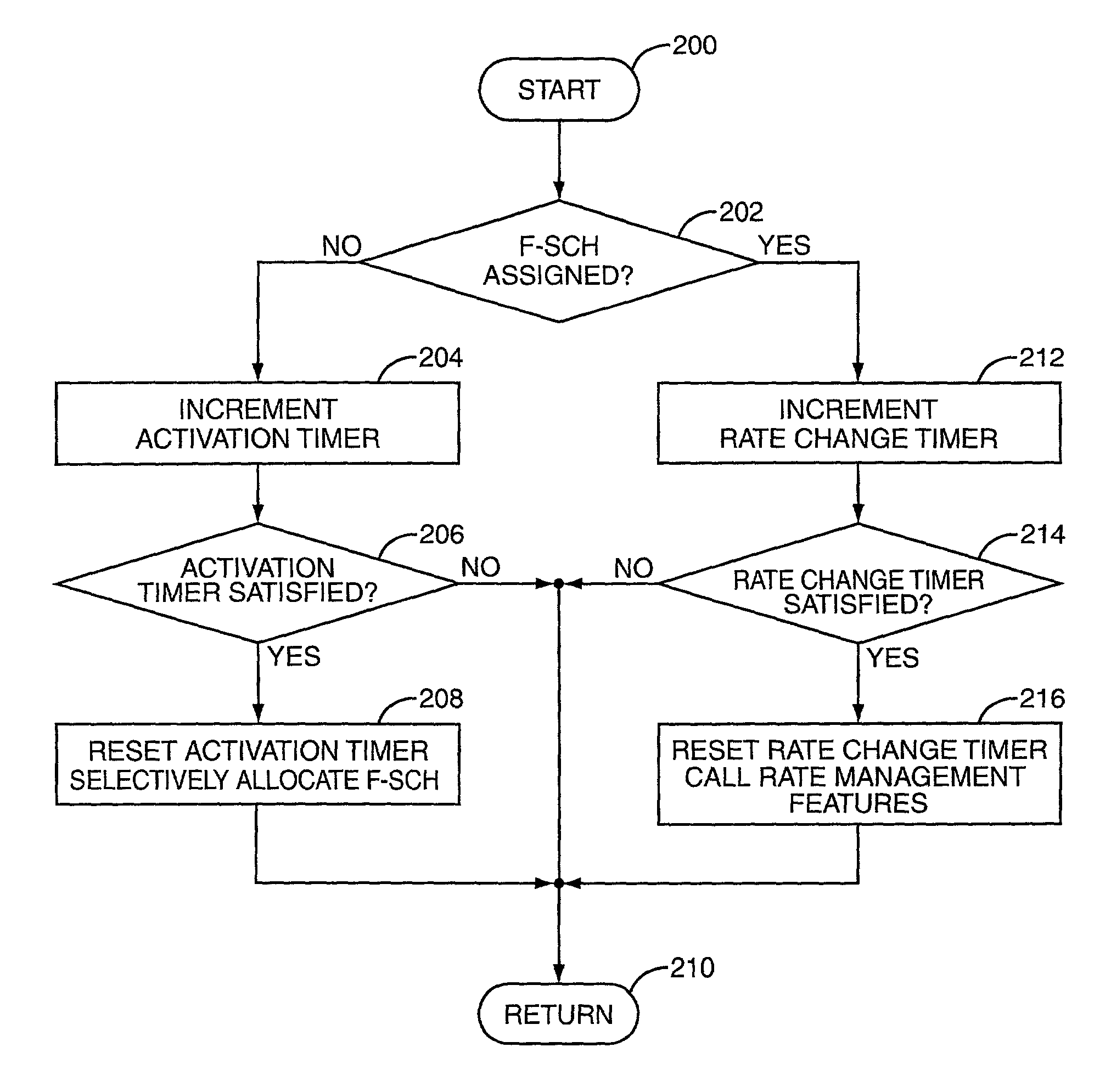
[0005]The present invention comprises a method and apparatus for managing radio channel allocation and configuration in a radio access network. In one aspect, the present invention provides rate management functions that dynamically adjust the data rate capacity of an allocated radio channel upwards or downwards to its most appropriate rate setting. The appropriateness of the current data rate setting may be evaluated in terms of channel utilization, observed error, or any combination thereof. By selecting the best matching of available data rate settings for allocated radio channels, the radio access network's resources are more efficiently utilized. So, rather than maintaining a high data rate capacity on a channel that is being underutilized or suffers from excessive error, that channel's data rate may be reduced and the freed resources put to better use elsewhere.

Problems solved by technology

While the demand for data services continues to grow, the resources available to provide such services are finite.
Thus, in contrast to older communication systems, these newer communication networks may allocate substantial resources to a single user, potentially reducing the total number of users that may be simultaneously supported.

Method used


Image

  • Triggered packet data rate change in a communication system
  • Triggered packet data rate change in a communication system
  • Triggered packet data rate change in a communication system

Examples


Embodiment Construction

[0016]The present invention may be applied to a variety of radio access network types. These network types include but are not limited to so-called third generation (3G) wireless cellular communication networks, such as those radio access networks based on the cdma2000 or W-CDMA standards. Thus, it should be understood that the following discussion of particular system types and implementations is only for illustrative purposes. It should also be understood that where illustrative variables are involved, such as various timers or counters, and minimum and maximum values, these value are configurable as specific implementations might require.

[0017]Turning now to the drawings, FIG. 1 illustrates a wireless communication network generally referred to the by numeral 10. The network 10 comprises a radio access network (RAN) 12, and a core network comprising a mobile switching center (MSC) 14 and associated home location register (HLR) 16, and a packet data serving node (PDSN) 18. The net...


PUM


Abstract

Communication traffic associated with one or more mobile terminals is monitored to efficiently manage allocated radio resources. A rate management technique dynamically adjusts allocated radio resources to increase or decrease the data rate capacity of allocated radio channels based on actual channel usage. In this manner, radio resources are more efficiently utilized because the amount of excess capacity allocated to individual subscribers is reduced. Monitoring communication traffic may also be used to determine whether additional radio channel resources are allocated to a given subscriber. For example, in a cdma2000 radio access network, subscribers are typically allocated fundamental radio channels and then assigned supplemental channels to access higher data rate services. By monitoring fundament channel traffic characteristics, such as the queue length or packet size of outgoing packet data, the radio access network can determine whether supplemental channel allocation is warranted.

Description

BACKGROUND OF THE INVENTION[0001]The present invention relates to wireless communication systems in general, and particularly relates to such systems that employ variable rate or variable bandwidth radio channels.[0002]As wireless communication systems evolve, the range of services offered by such systems expands. The increasing diversity, sophistication, and quality of available services have attracted a rapidly growing number of people who use wireless communications in their everyday lives. For example, today's mobile terminal user may subscribe to a wide range of voice and data services, including Internet access, email, and other data services in addition to more conventional voice services. It is expected that the demand for wireless communication services will continue to grow as new services are added and existing services are improved.[0003]While the demand for data services continues to grow, the resources available to provide such services are finite. These resources incl...

Claims


Application Information

Patent Timeline
Patent Type & Authority Patents(United States)
IPC IPC(8): H04J1/16H04J3/14H04L1/00H04L12/56H04L29/08H04W24/00H04W28/14H04W28/22H04W72/00H04W74/00
CPCH04L1/0002H04L1/0017H04W72/0486H04W28/14H04W28/22H04W28/04H04W72/52
Inventor GUPTA, PRAVEENRUTH, TODD
Owner TELEFON AB LM ERICSSON (PUBL)
Learn More