
Targeted stent placement and multi-stent therapy

a multi-stent, targeted technology, applied in the field of glaucoma, can solve the problems of headache, untreated blindness, and associated side effects, and achieve the effect of less expensive, faster and safer

Active Publication Date: 2007-03-20
GLAUKOS CORP
View PDF10 Cites 217 Cited by
  • Summary
  • Abstract
  • Description
  • Claims
  • Application Information

AI Technical Summary

Benefits of technology

The patent text describes a method for treating glaucoma by using a trabecular stent to lower intraocular pressure. The method involves creating a hole through the trabecular meshwork from Schlemm's canal into the anterior chamber of the eye. The stent can be made of biocompatible material and can be loaded with drugs for therapeutic effects. The method is faster, safer, and less expensive than current procedures. The technical effects of the patent text include reducing the need for multiple surgeries and the risk of complications, and providing a more effective treatment for glaucoma.

Problems solved by technology

Glaucoma is a group of eye diseases that causes pathological changes in the optic disk and corresponding visual field loss resulting in blindness if untreated.
However, there are secondary open-angle glaucomas that may include edema or swelling of the trabecular spaces (from steroid use), abnormal pigment dispersion, or diseases such as hyperthyroidism that produce vascular congestion.
However, these various drug therapies for glaucoma are sometimes associated with significant side effects, such as headache, blurred vision, allergic reactions, death from cardiopulmonary complications and potential interactions with other drugs.
However, long-term review of surgical results showed only limited success in adults.
In retrospect, these procedures probably failed secondary to repair mechanisms and a process of “filling in”.
The filling in is a detrimental effect of collapsing and closing in of the created opening throughput trabecular meshwork.
Once the created openings close, the pressure builds back up and the surgery fails.
However, the relatively small hole created by this trabeculopuncture technique exhibits a filling in effect and fails.
Although morbidity was zero in both trials, success rates did not warrant further human trials.
Failure again was from filling in of created defects in trabecular meshwork by repair mechanisms.
The risk of placing a glaucoma drainage implant also includes hemorrhage, infection and postoperative double vision that is a complication unique to drainage implants.
The above embodiments and variations thereof have numerous disadvantages and moderate success rates.
They involve substantial trauma to the eye and require great surgical skill by creating a hole over the full thickness of the sclera / cornea into the subconjunctival space.

Method used


Image

  • Targeted stent placement and multi-stent therapy
  • Targeted stent placement and multi-stent therapy
  • Targeted stent placement and multi-stent therapy

Examples


example no.1

Example No. 1

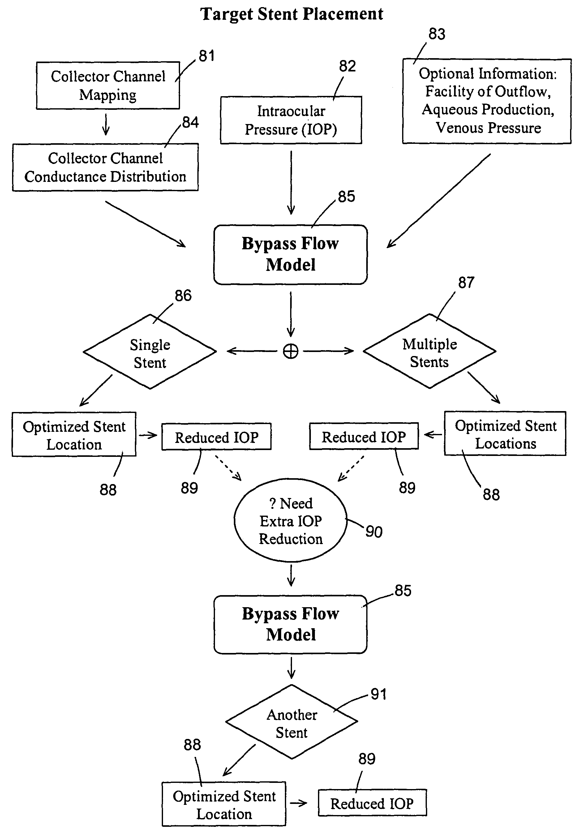
[0058]This example illustrates an IOP simulation for a normal individual, “uniform” outflow, and episcleral venous pressure of 10 mmHg. The input conditions comprise an episcleral venous pressure of about 10 mmHg, an aqueous production rate of about 2.4 μl / min, a trabecular meshwork resistance of about 1.25 mmHg / (μl / min), a collector channel resistance of about 1.25 mmHg / (μl / min) that is assumed uniformly distributed in this simulation, a Schlemm's canal resistance of about 1.0 mmHg / (μl / min) / mm, a Schlemm's canal circumferential length of about 36 mm, an aqueous humor viscosity of about 0.72 cP, and Schlemm's canal having a substantially elliptic cross section with a height of about 20 μm and a width of about 230 μm. From the bypass flow model, it is determined that this patient has an outflow facility of about 0.4 μl / min / mmHg and an intraocular pressure of about 16 mmHg.

example no.2

Example No. 2

[0059]This example illustrates an IOP simulation for a normal individual, “uniform” outflow, and episcleral venous pressure of 9 mmHg. The input conditions comprise an episcleral venous pressure of about 9 mmHg, an aqueous production rate of about 2.4 μl / min, a trabecular meshwork resistance of about 1.25 mmHg / (μl / min), a collector channel resistance of about 1.25 mmHg / (μl / min) that is assumed uniformly distributed, a Schlemm's canal resistance of about 1.0 mmHg / (μl / min) / mm, a Schlemm's canal circumferential length of about 36 mm, an aqueous humor viscosity of about 0.72 cP, and Schlemm's canal having a substantially elliptic cross section with a height of about 20 μm and a width of about 230 μm. From the bypass flow model, it is determined that this patient has an outflow facility of about 0.4 μl / min / mmHg and an intraocular pressure of about 15 mmHg.

example no.3

Example No. 3

[0060]This example illustrates an IOP simulation for a normal individual, “uniform” outflow, with bi-directional bypass. The input conditions comprise an episcleral venous pressure of about 9 mmHg, an aqueous production rate of about 2.4 μl / min, a trabecular meshwork resistance of about 1.25 mmHg / (μl / min), a collector channel resistance of about 1.25 mmHg / (μl / min) that is assumed uniformly distributed, a Schlemm's canal resistance of about 1.0 mmHg / (μl / min) / mm, a Schlemm's canal circumferential length of about 36 mm, an aqueous humor viscosity of about 0.72 cP, and Schlemm's canal having a substantially elliptic cross section with a height of about 20 μm and a width of about 230 μm, and a bi-directional bypass through the trabecular meshwork. From the bypass flow model, it is determined that this patient has an outflow facility of about 0.51 μl / min / mmHg and an intraocular pressure of about 13.8 mmHg.


PUM


Abstract

A trabecular flow model for producing treatment recommendations for patients with elevated intraocular pressure is disclosed. One method includes providing intraocular pressure measurements for a patient; providing aqueous cavity information, such as collector channel resistance and Schlemm's canal resistance, and determining a treatment recommendation for the patient based on the aforementioned parameters.

Description

CROSS REFERENCE TO RELATED APPLICATIONS[0001]This application claims the priority benefits of U.S. Provisional Application No. 60 / 410,646, filed Sep. 14, 2002; U.S. Provisional Application No. 60 / 432,861, filed Dec. 12, 2002; and U.S. Provisional Application No. 60 / 438,372, filed Jan. 7, 2003. The entireties of all of these documents are hereby incorporated by reference.FIELD OF THE INVENTION[0002]The invention generally relates to medical devices and methods for the reduction of elevated pressure in an eye of a patient. More particularly, the invention relates to the treatment of glaucoma by means of targeted stent placement and multi-stent therapy in an ab externo and / or ab interno procedures for bypassing diseased trabecular meshwork.BACKGROUND OF THE INVENTION[0003]About two percent of people in the United States have glaucoma. Glaucoma is a group of eye diseases that causes pathological changes in the optic disk and corresponding visual field loss resulting in blindness if untr...

Claims


Application Information

Patent Timeline
Patent Type & Authority Patents(United States)
IPC IPC(8): A61M5/00
CPCA61F9/00781A61F2/82A61B2034/105A61B2034/104A61B2034/101
Inventor ZHOU, JIANBOSMEDLEY, GREGORY
Owner GLAUKOS CORP
Learn More