
Control system for continuously variable transmission of vehicle

a technology of continuously variable transmission and control system, which is applied in the direction of hybrid vehicles, road transportation, gearing, etc., can solve the problems of inconvenient determination of the accurate value of the clamping pressure in advance, the efficiency of the power transmission is degraded, and the friction coefficient is not constant, so as to prevent or suppress the change of the entire drive torque of the vehicle, the learning range of the clamping pressure can be enlarged, and the effect of preventing or suppressing the change of th

Inactive Publication Date: 2007-03-13
TOYOTA JIDOSHA KK
View PDF14 Cites 11 Cited by
  • Summary
  • Abstract
  • Description
  • Claims
  • Application Information

AI Technical Summary

Benefits of technology

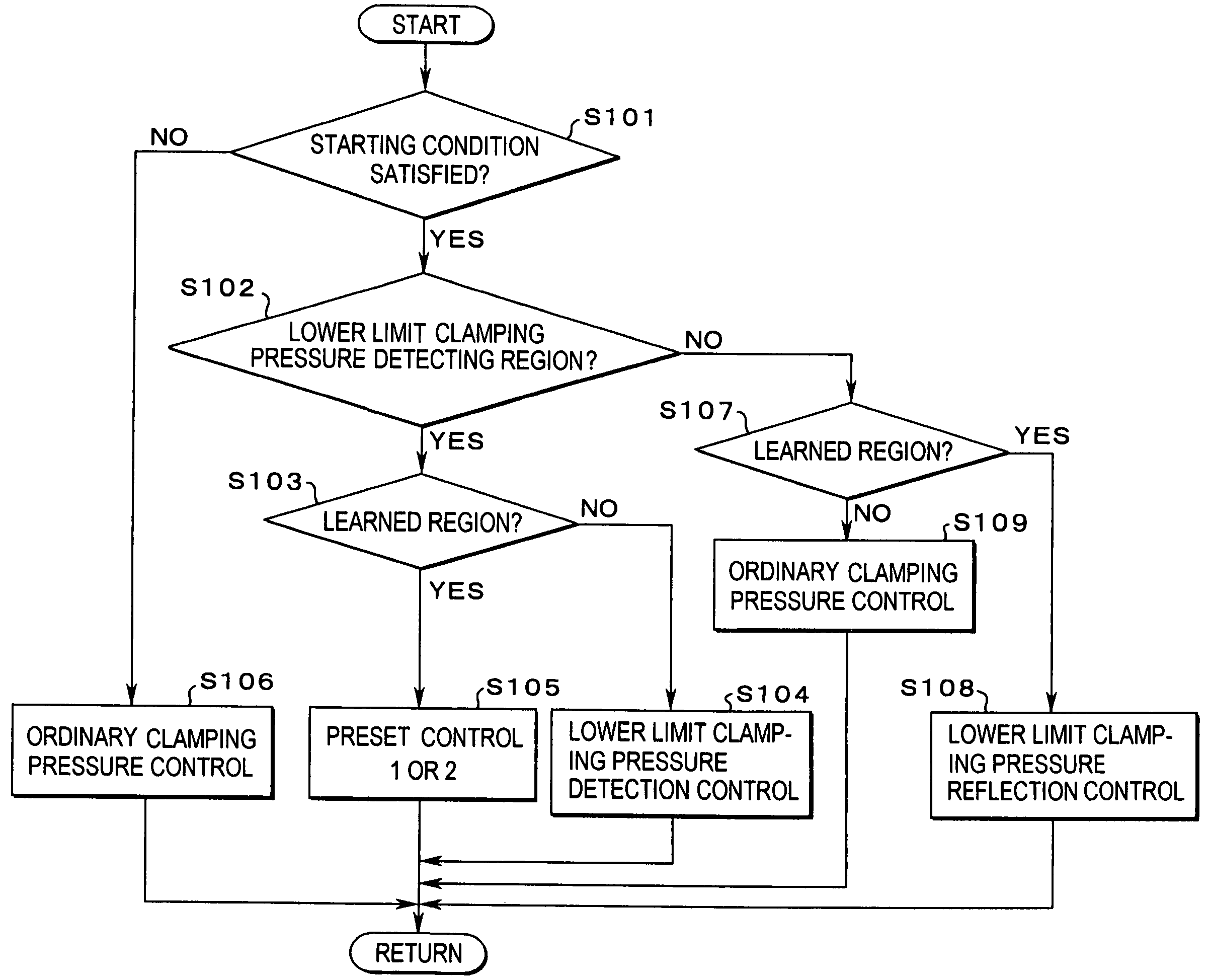
The present invention provides a control system for a continuously variable transmission of a vehicle that can learn the clamping pressure of rotary members to clamp the transmission member in every operating state of the prime mover connected to the input side of the continuously variable transmission. The system can also suppress changes in torque resulting from changes in the operating state of the prime mover. The learning of the clamping pressure is carried out by calculating the difference between the clamping pressure in the case of a lower limit and the current operating state of the prime mover. The system can also control the speed of the prime mover to prevent or suppress deviation from the object range of the learning. The technical effects of the invention include a wider learning range of the clamping pressure, improved fuel consumption, and durability of the continuously variable transmission.

Problems solved by technology

On the contrary, there arises a disadvantage that a power is consumed more than necessary for establishing a high pressure or that the efficiency of power transmission is degraded.
However, the variable such as the input torque as well as the constant such as the friction coefficient are not constant due to the individual difference, the aging or the estimated error.
Therefore, it is difficult to determine an accurate value of the clamping pressure in advance.
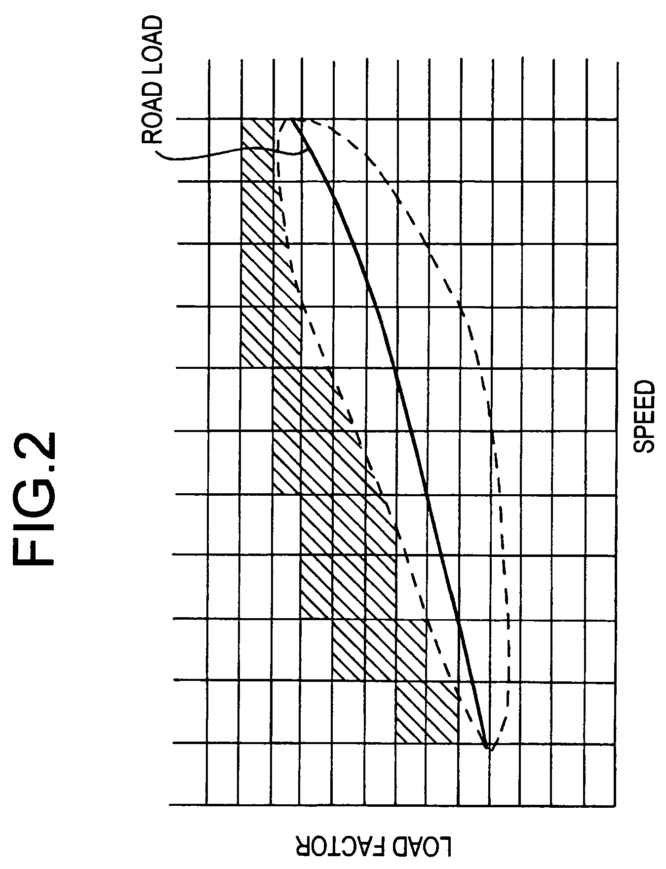
Therefore, the slip limit or the clamping pressure of various kinds of operating state cannot be determined or learned over a wide range unless the operating state of the continuously variable transmission or the vehicle having the continuously variable transmission changes widely.

Method used


Image

  • Control system for continuously variable transmission of vehicle
  • Control system for continuously variable transmission of vehicle
  • Control system for continuously variable transmission of vehicle

Examples


Embodiment Construction

[0037]This invention will be described in connection with its specific examples. First of all, here will be described a continuously variable transmission of a vehicle to which the invention is applied. The present invention is applied to: a belt-type continuously variable transmission, in which a belt functioning as a transmission member is applied to a pulley functioning as a rotary member and is clamped by sheaves of the pulley; or a toroidal type (traction type) continuously variable transmission, in which a power roller functioning as a transmission member is clamped by discs of input and output sides functioning as rotary members through oil (i.e., a traction oil), and in which a torque is transmitted by a shearing force of traction oil. One example of a drive mechanism including a belt type continuously variable transmission 1 is illustrated in FIG. 6. An engine 2 functioning as a prime mover, and a motor generator 3 having a power generating function for adding and reducing ...


PUM


Abstract

The control system comprises: an operating state changing mechanism for an operating state of the prime mover in response to a satisfaction of learning execution condition of the clamping pressure; a torque change suppressing mechanism for suppressing a change in a torque resulting from the change in the operating state of the prime mover; and a clamping pressure learning device for learning the clamping pressure in the operating state of the prime mover after the change, while the operating state of the prime mover is being changed and the change in the torque resulting from the change in the operating state of the prime mover is being suppressed by the torque change suppressing mechanism.

Description

BACKGROUND OF THE INVENTION[0001]1. Field of the Invention[0002]This invention relates to a control system for setting a clamping pressure of a continuously variable transmission which is mounted on a vehicle, neither too much nor too little, by learning the clamping pressure in every operating state of the vehicle or a prime mover, and by reflecting the learned result of in the control of the clamping pressure.[0003]The disclosure of Japanese Patent Application No. 2004-041756 filed on Feb. 18, 2004 including specification, drawings and claims is incorporated herein by reference in its entirety.[0004]2. Discussion of the Related Art[0005]A belt type continuously variable transmission or a traction type continuously variable transmission transmits a torque by utilizing a frictional force between a belt and pulleys or a shearing force of traction oil between discs and rollers. Accordingly, a torque capacity of the continuously variable transmission of those kinds is set in accordance...

Claims


Application Information

Patent Timeline
Patent Type & Authority Patents(United States)
IPC IPC(8): F16H61/662B60K6/44F02D29/00B60K6/48B60K6/52B60K6/543B60W10/06B60W10/08B60W10/10B60W20/00F02D29/02F16H9/00F16H59/14F16H59/18F16H59/40F16H59/42F16H59/66F16H59/68F16H59/72F16H61/00F16H61/02F16H61/66F16H61/664F16H63/40F16H63/50
CPCB60K6/365B60K6/48B60K6/543B60W10/10F16H61/66272B60L2260/14Y10T477/6242F16H2061/66277Y02T10/6221Y02T10/76Y10T477/624Y10T477/6939F16H2061/0087Y02T10/62
Inventor OSHIUMI, YASUHIROIWATSUKI, KUNIHIROAMAYA, TAKAYUKI
Owner TOYOTA JIDOSHA KK
Learn More